Supercharger with controllable hydraulic pressure and flow output

A flow output, liquid pressure technology, applied in the direction of fluid pressure converter, mechanical equipment, etc., can solve the problems of large hydraulic shock, low work efficiency, large floor space, etc., to achieve improved work efficiency and safety performance, less floor space Small, simplified design

Inactive Publication Date: 2011-03-30
云南兴长江实业有限公司
View PDF0 Cites 9 Cited by
  • Summary
  • Abstract
  • Description
  • Claims
  • Application Information

AI Technical Summary

Problems solved by technology

[0006] At present, the commonly used supercharger is a horizontal single-cylinder supercharger, which occupies a large area and has an output flow rate of 30L / min. The flow rate is small and the working efficiency is low.
The output pressure and flow are pulsating, and the hydraulic shock is large

Method used


Image

  • Supercharger with controllable hydraulic pressure and flow output
  • Supercharger with controllable hydraulic pressure and flow output
  • Supercharger with controllable hydraulic pressure and flow output

Examples


Embodiment Construction

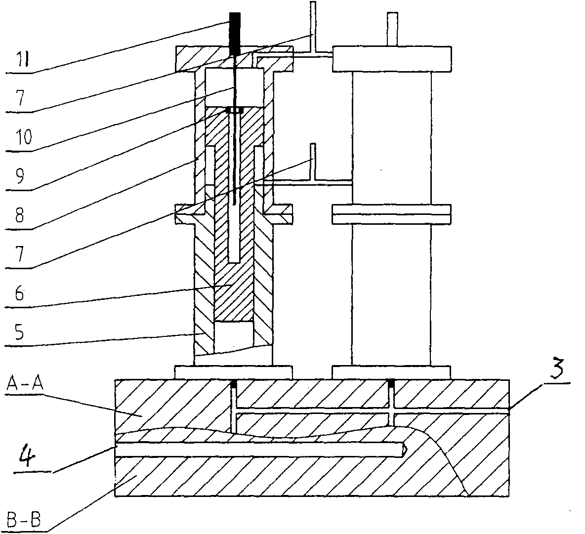
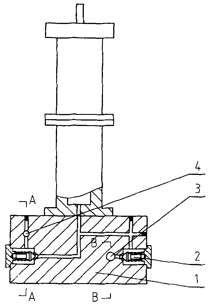
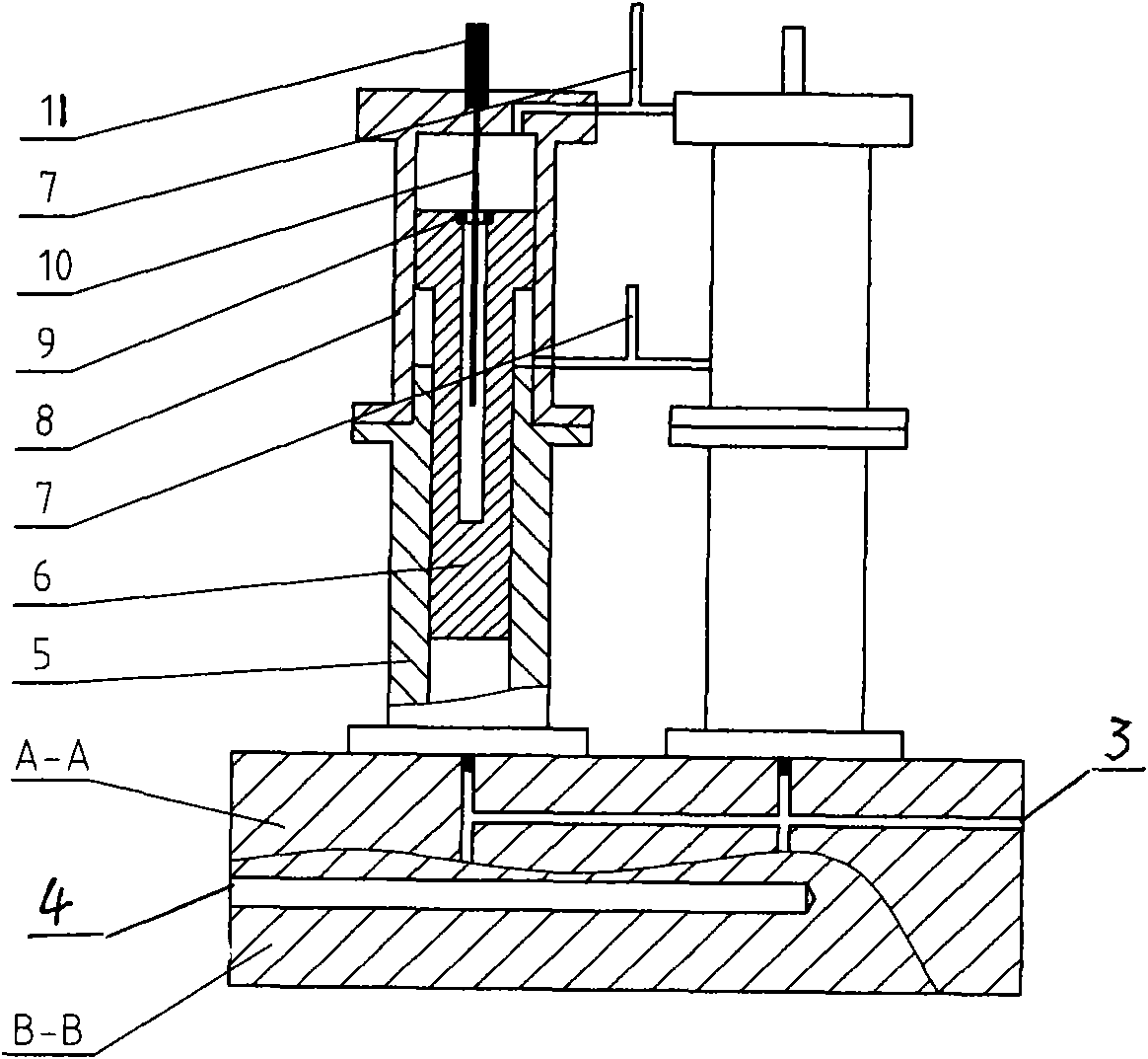
[0022] A pressure booster with controllable output of liquid pressure and flow is composed of two booster cylinders and a valve seat (1) connecting the two booster cylinders. Wherein, each booster cylinder is composed of the upper hydraulic cylinder (8), the lower plunger cylinder (5), the piston rod (6) and the displacement sensor, and the magnetic ring (9) of the displacement sensor is installed on the piston rod ( 6) The center hole port, the sensing rod (10) is inserted into the center hole of the piston rod (6) through the magnetic ring (9), and the sensor electronic head (11) at the top end of the sensing rod (10) is fixed on the hydraulic cylinder (8) top.

[0023] Two upright booster cylinders are installed on the valve seat (1), and there are water inlet hole (4), water outlet hole (3), check valve (2) in the valve seat (1), water inlet hole (4) and The external water tank is connected, and the water outlet (3) is connected with the hydraulic test tube machine. The ...


PUM


Abstract

The invention relates to a supercharger with controllable hydraulic pressure and flow output, wherein a twin-charger high-pressure fluid output structure is adopted, and the diameter and the stroke of a piston and a plunger of each charger are increased so as to meet a work pressure output requirement and simultaneously improve output flow, which is 10 times that of the traditional supercharger. A phase different between the operation cycles of the pistons of the two chargers is 180 degrees, the output high-pressure fluid enters a valve seat (1), and a waterway channel in the valve seat (1) is designed in a bridge type loop structure which ensures that the output high-pressure fluid is stable and balanced in flow. A displacement transducer control technology is introduced to meet an automation requirement of a water pressure test-tube engine test, and the work efficiency and the safety performance of a detection test on an oil transferring pipeline are greatly improved.

Description

1. Technical field [0001] The invention relates to a supercharger, in particular to a supercharger which can be controlled by liquid pressure and flow output. 2. Background technology [0002] The booster cylinder is composed of a hydraulic cylinder and a plunger cylinder. It uses the difference in effective area between the piston and the plunger to obtain high pressure in a local area of ​​the hydraulic system. Its upper end is a piston, and the lower end is a plunger, and the piston and the plunger form a part. [0003] When the liquid pressure input to the hydraulic cylinder is p (liquid), the diameter of the piston is D, the diameter of the plunger cylinder is d, and the output pressure p (column), its value is equal to: [0004] p (column) = p (liquid) (D / d) 2nm [0005] According to this principle, if the diameters of the piston and plunger are reasonably determined, the supercharger can output the required high-pressure fluid. [0006] At present, the commonly use...

Claims


Application Information

Patent Timeline
Patent Type & Authority Applications(China)
IPC IPC(8): F15B3/00
Inventor 杨力李连成张海波
Owner 云南兴长江实业有限公司
Why Eureka
Try Eureka