
Two-free endpoint dynamic vibration absorber

A dynamic vibration absorber and endpoint technology, which is applied in the field of dynamic vibration absorbers, can solve the problems of reducing the weight of large dynamic vibration absorbers, and achieve the effects of convenient installation and layout, wide application range, and weight reduction

Active Publication Date: 2011-03-30
JIANGSU UNIV
View PDF8 Cites 12 Cited by
  • Summary
  • Abstract
  • Description
  • Claims
  • Application Information

AI Technical Summary

Problems solved by technology

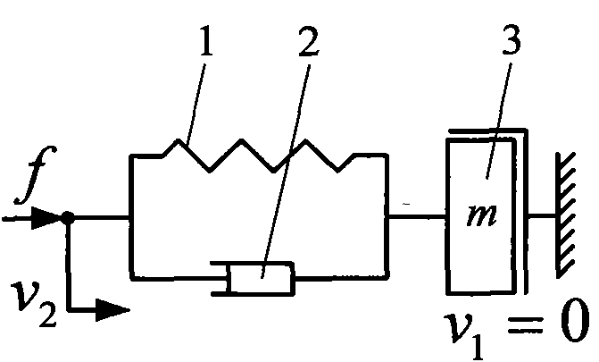
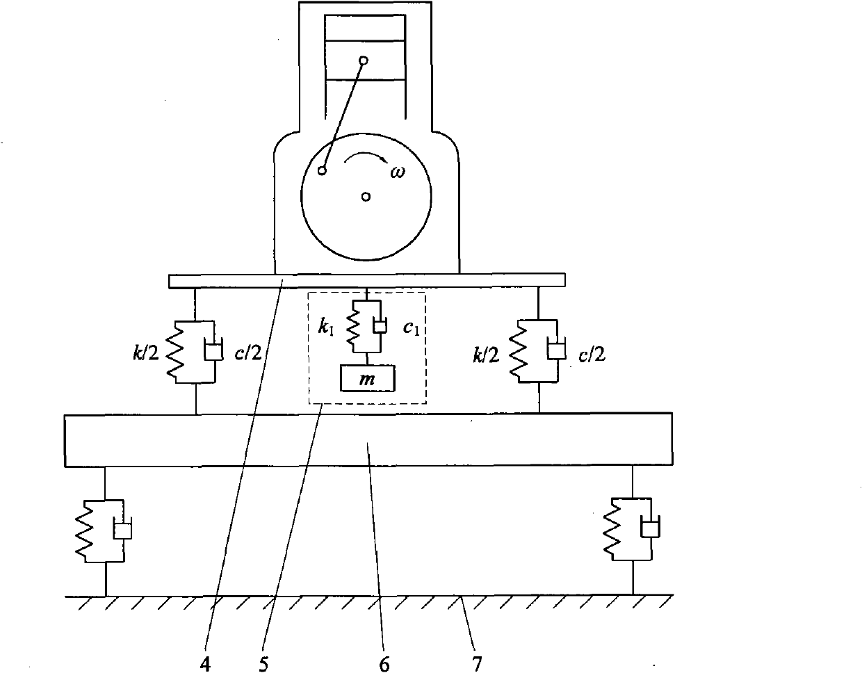
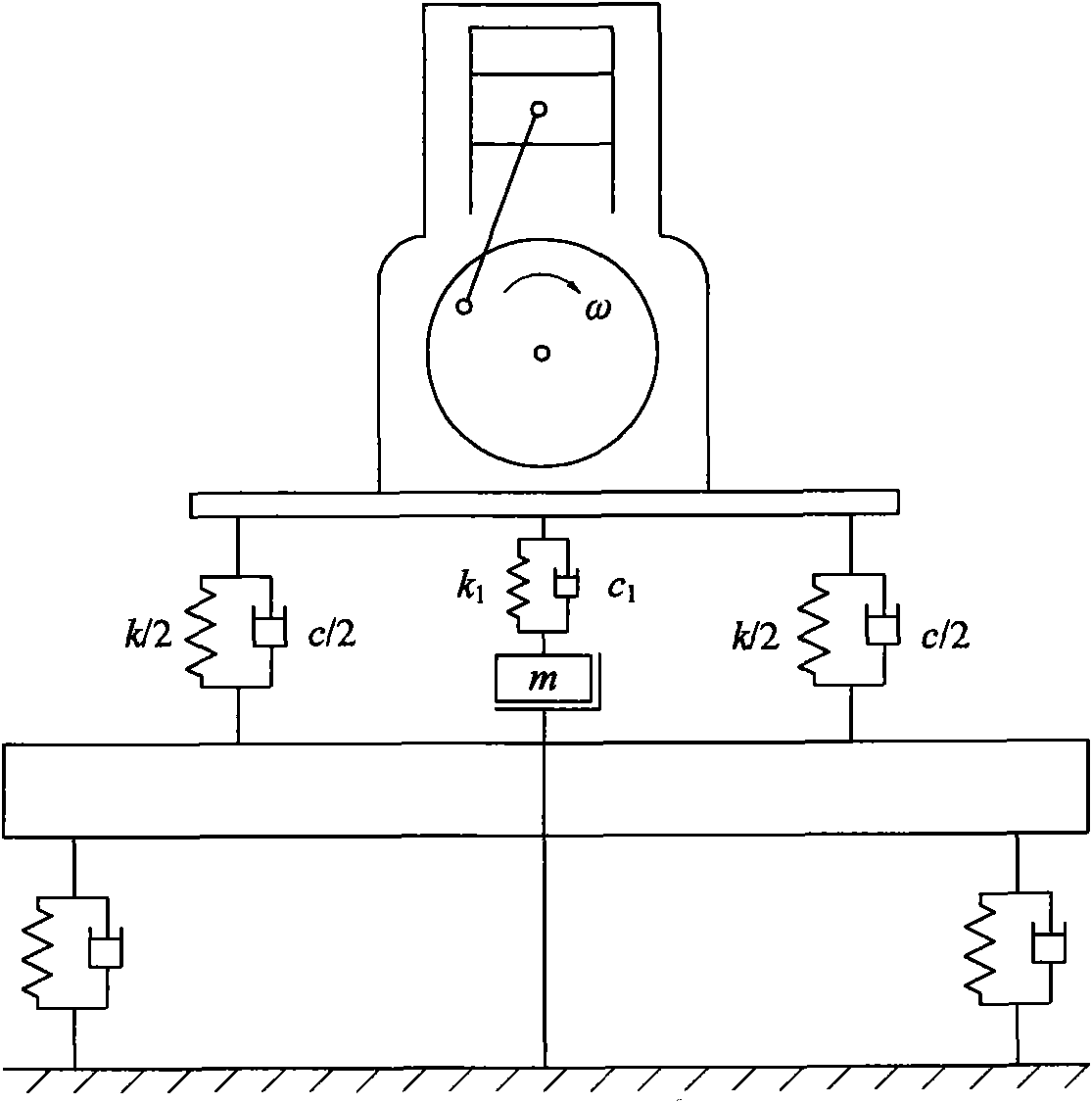
[0008] The technical problem to be solved by the present invention is: let the dynamic vibration absorber have two free endpoints, so that the vibration absorber can be applied to occasions where the endpoints cannot be grounded as a reference point, and expand the application range of the dynamic vibration absorber; the dynamic vibration absorber has two endpoints Finally, one end is connected to the main vibration system, and the other end can freely choose the connection point, so that the vibration absorber can be placed horizontally, vertically and obliquely, which is convenient for the installation and arrangement of the vibration absorber, and absorbs the vibration of the main vibration system in any direction; the use of inertial mass Accumulators are much lighter than mass components, reducing the weight of large dynamic shock absorbers

Method used


Image

  • Two-free endpoint dynamic vibration absorber
  • Two-free endpoint dynamic vibration absorber
  • Two-free endpoint dynamic vibration absorber

Examples


Embodiment 1

[0049] The dynamic vibration absorber 34 with two free ends includes a spring 1 , a damper 2 and a rack-type inertial mass accumulator 9 . The spring 1 is set outside the outer cylinder of the damper 2, the spring 1 is connected coaxially with the damper 2, one end of the spring 1 is fixedly connected with the piston rod of the damper 2, and the other end of the spring 1 is fixedly connected with the outer cylinder of the damper 2 ; The piston rod of the damper 2 is coaxially fixedly connected with the rack 15 of the rack type inertial mass accumulator 9 .

[0050] The rack type inertial mass accumulator 9 includes a box body 10, a flywheel A11, a gear shaft A12, a large gear 13, a gear shaft B14 and a rack 15, wherein the rack 15 is placed in the dovetail groove on the box body 10, and the same as the gear The shaft B14 is meshed, the large gear 13 is coaxially connected with the gear shaft B14, and meshed with the gear shaft A12, and the flywheel A11 is coaxially connected w...

Embodiment 2

[0058] The dynamic vibration absorber 34 with two free ends includes a spring 1 , a damper 2 and a torsional inertial mass accumulator 16 . The spring 1 is set outside the outer cylinder of the damper 2, the spring 1 is connected coaxially with the damper 2, one end of the spring 1 is fixedly connected with the piston rod of the damper 2, and the other end of the spring 1 is fixedly connected with the outer cylinder of the damper 2 ; The piston rod of the damper 2 is hinged with the fork 17 of the torsional inertial mass accumulator 16, and in the equilibrium position, the piston rod of the damper 2 and the fork 17 are perpendicular to each other.

[0059] The torsional inertial mass accumulator 16 includes a swing rod 17, a base 18, a cycloid steel ball reducer 19 and a flywheel B20.

[0060] The cycloidal steel ball reducer 19 includes an input shaft 21 , a cycloidal steel ball transmission mechanism, an output shaft 28 , a housing 29 and a preload nut 33 .

[0061] The con...


PUM


Abstract

The invention discloses a two-free endpoint dynamic vibration absorber, relating to the technical field of dynamic vibration absorber. The two-free endpoint dynamic vibration absorber comprises a spring (1), a damper (2) and an inertial mass energy accumulator (8); wherein the spring (1) is connected with the damper (2) in parallel and then is connected with the inertial mass energy accumulator (8) in series; the spring (1) is a helical compression one, and the damper (2) is a drum-type hydraulic one. The invention can be applied to the occasion that an endpoint can not be taken as a reference point and grounded and has wider application range compared with the traditional dynamic vibration absorber; the vibration absorber is provided with two free endpoints and can be placed horizontally, vertically and obliquely, vibration of master vibrator at any direction can be absorbed, thus being convenient to mount the vibration absorber; the inertial mass energy accumulator has the function of amplifying mass property, the weight thereof is far lighter than a mass element, thus greatly reducing the weight of large-scale dynamic vibration absorber.

Description

technical field [0001] The invention relates to the technical field of dynamic vibration absorbers, in particular to a dynamic vibration absorber with two free end points. Background technique [0002] Dynamic vibration absorbers are also called tuned mass dampers (Tuned mass dampers, TMD). The form, dynamic parameters and coupling relationship with the main vibration system can change the vibration state of the main vibration system, thereby reducing the forced vibration response of the main vibration system in the expected frequency band. Because of its simple structure and easy implementation, it can effectively suppress the vibration of equipment with small frequency changes, so it is widely used in various mechanical equipment in various industries such as transportation, industrial machinery, construction bridges, etc., and has become the most commonly used vibration control method. One of the important means. In recent years, although the research and application of...

Claims


Application Information

Patent Timeline
IPC IPC(8): F16F15/02
Inventor 陈龙张孝良聂佳梅江浩斌汪若尘
Owner JIANGSU UNIV
Learn More