Integral insulating joint

An insulating joint and integral technology, applied in the direction of pipes/pipe joints/pipes, passing components, mechanical equipment, etc., can solve the problems of difficult sealing effect of insulating gasket 4, difficult sealing effect of insulating gasket 4, easy damage, etc. , to achieve the effect of excellent insulation and sealing effect

Inactive Publication Date: 2011-03-30
CHANGSHU NO 2 CHEM ENG EQUIP PLANT
View PDF7 Cites 12 Cited by
  • Summary
  • Abstract
  • Description
  • Claims
  • Application Information

AI Technical Summary

Problems solved by technology

However, there is a deficiency in this patent that it is difficult for the insulating gasket 4 to provide insulation and an ultimate sealing effect between the upper and lower conduits 6 and 1, that is to say, the insulating gasket 4 is difficult to achieve an ideal sealing effect.
And, the insulating device 3 of this patent is an integral structure, which has a quick effect on installation and construction, but it cannot guarantee the reliability of the seal, because there must be a fit gap between the insulating device 3 and the insulating gasket 4. , The gas in the downcomer 6 and 1 leaks out from between the mating surfaces of the insulating gasket 4, and then leaks out from the fitting gap between the insulating gasket 5 and the insulating device 3
[0004] An integral insulating joint recommended by utility model patent authorization announcement number CN2586861Y improves the sealing performance between the insulating gasket (patent called inner gasket) and the upper and lower conduits compared with the previous patent, but the gasket (patent The structure of the outer gasket) is not superior to that of the previous patent, and the insulating gasket equivalent to the insulating device of the previous patent also has the shortcomings of the previous patent
Therefore, if the structure of the small-diameter insulating joint in the prior art is used, not only the first-time yield in the process of processing is only about 50%, but also in the process of transportation and installation, it is easy to be damaged due to the large diameter and dead weight.

Method used


Image

  • Integral insulating joint
  • Integral insulating joint
  • Integral insulating joint

Examples


Embodiment Construction

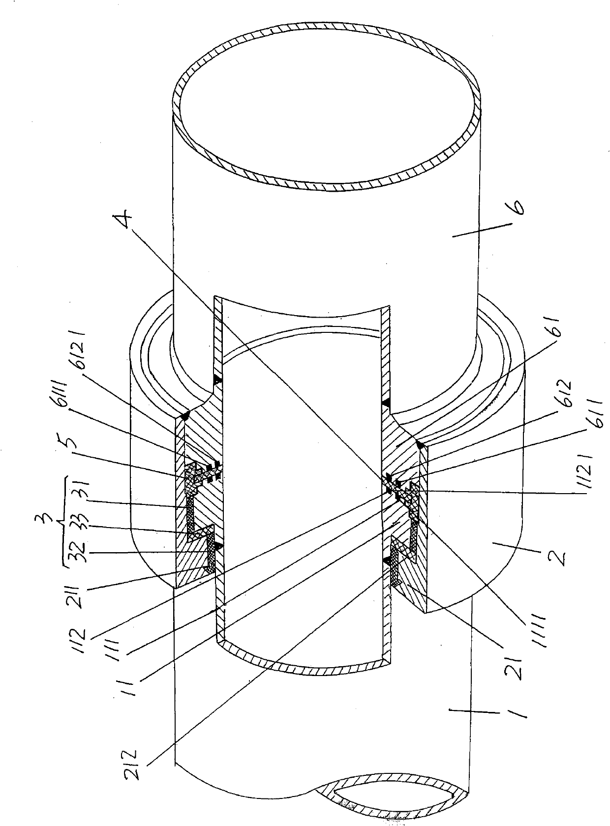
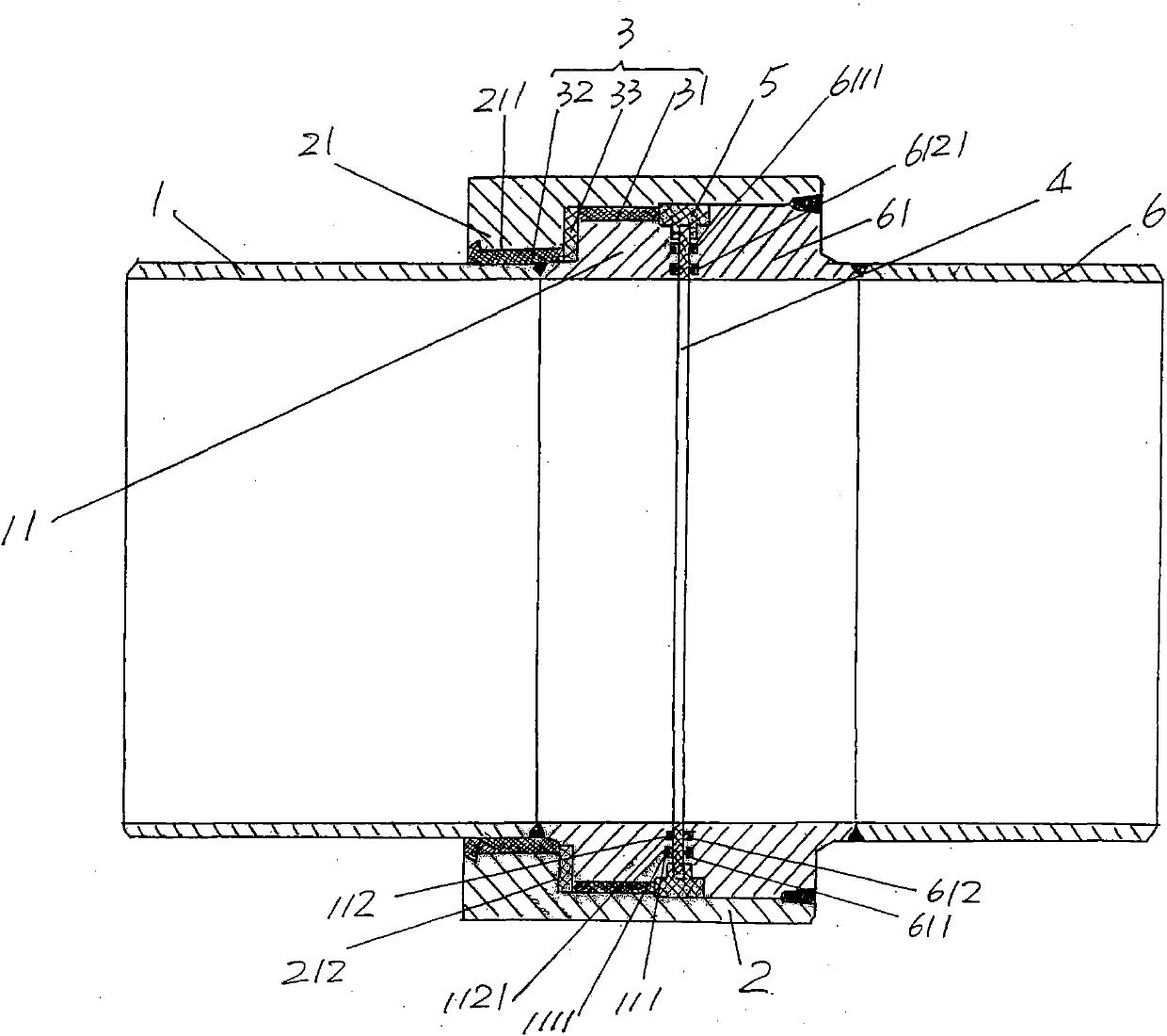
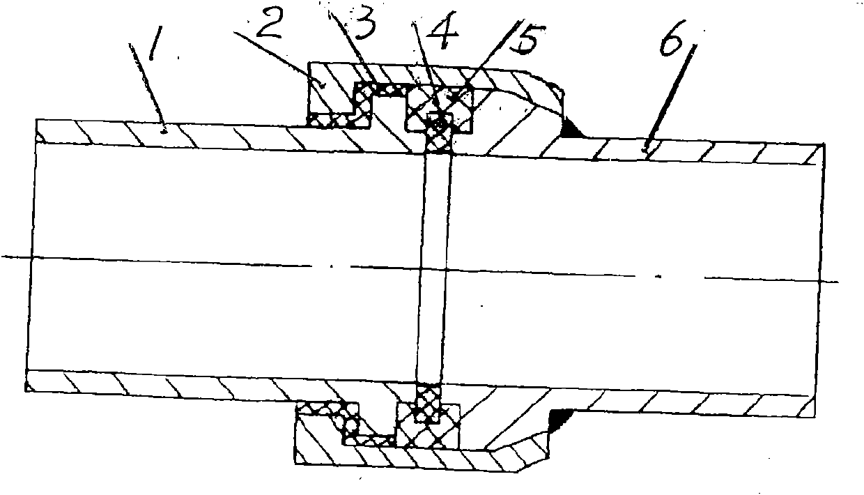
[0017] please see figure 1 and figure 2 , the upper and lower conduits 6, 1 are provided, the end of the lower conduit 1 towards the end of the upper conduit 6 is formed with a lower conduit flange 11 by welding, and at the side of the lower conduit flange 11 facing the upper conduit 6 The surface is provided with a first sealing ring groove 111 and a second sealing ring groove 112 , the first sealing ring groove 111 is embedded with a first sealing ring 1111 , and the second sealing ring groove 112 is embedded with a second sealing ring 1121 . Similarly, an upper conduit flange 61 is formed by welding at the end of the upper conduit 6 towards the end of the lower conduit 1, and the surface on the side of the upper conduit flange 61 facing the lower conduit 1 is toward the side of the lower conduit flange 11. A third sealing ring groove 611 and a fourth sealing ring groove 612 are opened on one side surface, a third sealing ring 6111 is embedded in the third sealing ring gr...


PUM


Abstract

The invention discloses an integral insulating joint belonging to pipeline fittings and comprising an upper conduit, a lower conduit, a casing, an insulating device, an insulating gasket and a sealing pad, wherein a lower conduit flange is arranged on the lower conduit; and an upper conduit flange is arranged on the upper conduit. The integral insulating joint is characterized in that a first sealing ring groove and a second sealing ring groove are arranged on the surface on one side of the lower conduit flange; a first sealing ring and a second sealing ring are embedded into the first sealing ring groove and the second sealing ring groove; a third sealing ring groove and a fourth sealing ring groove are arranged on the surface at the other side of the upper conduit flange; a third sealing ring and a fourth sealing ring are embedded into the third sealing ring groove and the fourth sealing ring groove; the insulating device comprises a first insulated filling layer, a second insulated filling layer and a sealing washer; the first insulated filling layer is positioned between the external circular surface of the lower conduit flange and the inner wall of the casing; the second insulated filling layer is positioned between the outer wall of the lower conduit and the first surface of a step of the casing; and the sealing washer is arranged between the second inner surface of the step and the lower conduit flange. The invention has the advantages of excellent insulating performance and no phenomena of damaging to the insulating and the sealing.

Description

technical field [0001] The invention belongs to the technical field of pipeline fittings, and in particular relates to an insulating joint, which is applied to gas transmission and distribution pipelines and oil transmission pipelines to implement insulation and isolation between pipelines. Background technique [0002] In view of the shortcomings of large volume, heavy weight, weak pressure bearing capacity, poor sealing and insulation performance in gas transmission and distribution pipelines, gas pressure regulating stations, oil transmission pipelines and pressure regulating stations in the past, the use of flange structures as insulating joints , so there are many insulating joints used in the above-mentioned occasions in the Chinese patent literature. [0003] The utility model patent authorization announcement number CN2375848Y discloses an integral type insulating joint, and its structure consists of image 3 As shown, the downcomer 1 is inserted into the insulating ...

Claims


Application Information

Patent Timeline
Patent Type & Authority Applications(China)
IPC IPC(8): F16L25/02
Inventor 陶金龙张诚周彩明
Owner CHANGSHU NO 2 CHEM ENG EQUIP PLANT
Why Eureka
Try Eureka