Fuel reactor device for chemical-looping combustion

A technology of fuel reactor and chemical looping combustion, which is applied in the direction of using non-combustion exothermic chemical reaction to generate heat, exothermic chemical reaction heat generation, heating fuel, etc., which can solve the problems of high cost of separation and recovery

Inactive Publication Date: 2011-03-30
SOUTHEAST UNIV
View PDF0 Cites 6 Cited by
  • Summary
  • Abstract
  • Description
  • Claims
  • Application Information

AI Technical Summary

Problems solved by technology

CO in flue gas 2 Often diluted with large amounts of nitrogen, CO 2 The cost of separation and recovery is very high

Method used


Image

  • Fuel reactor device for chemical-looping combustion
  • Fuel reactor device for chemical-looping combustion
  • Fuel reactor device for chemical-looping combustion

Examples


Embodiment 1

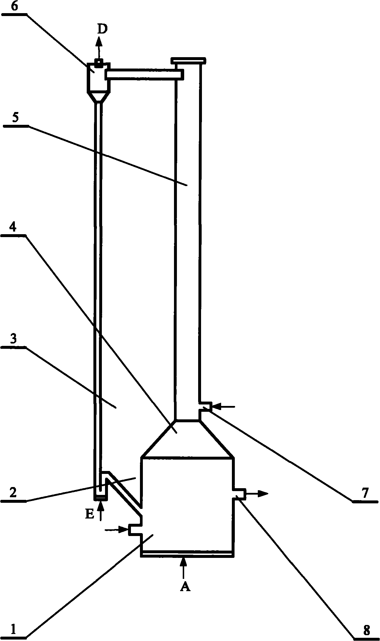
[0061] A fuel reactor device for implementing the chemical looping combustion described in claim 1, consisting of a mixing reaction chamber, an overflow tank, a transition section, a riser and a carbon dioxide separator, and the riser is connected to the mixing reaction chamber through the transition section , the lower end of the riser is provided with a feed port, and the upper end of the riser is connected with the upper end of the carbon dioxide separator, and the lower end of the carbon dioxide separator is connected with the mixing reaction chamber through an overflow tank. The lower end of the mixing reaction chamber is provided with an air distribution plate. The lower end of the mixing reaction chamber is provided with a solid fuel inlet. A discharge port is provided outside the mixing reaction chamber. The lower end of the overflow tank is provided with a loose air outlet. See attached figure 1 .

Embodiment 2

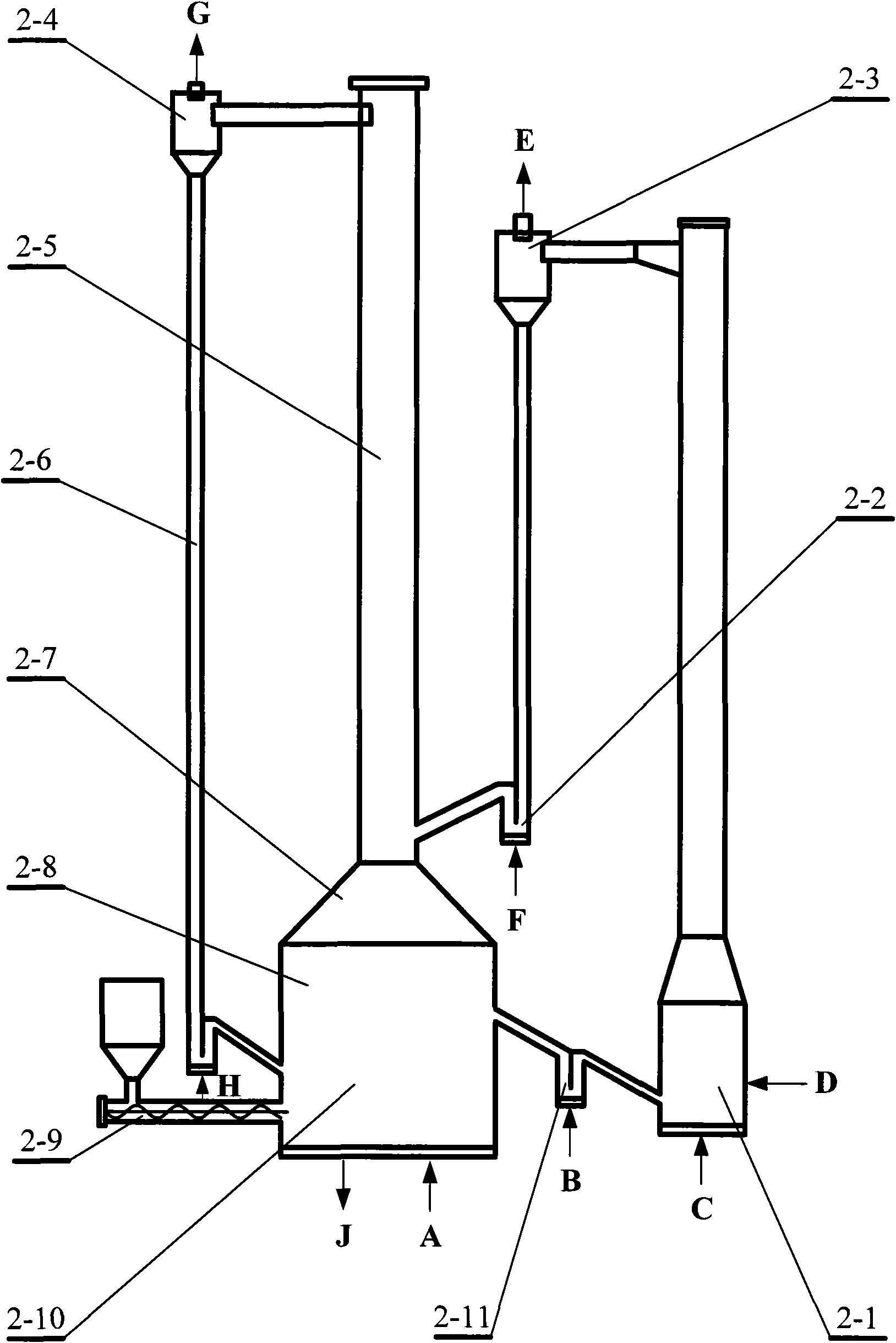
[0063] A chemical looping combustion method utilizing the present invention and using gaseous fuel is characterized in that Ni is placed in the air reactor, and fluidizing air is passed into the lower end E of the air reactor 2-1, and the operating temperature of the air reactor 2-1 can be Controlled at about 800°C ~ 1250°C, NiO is obtained after Ni reacts with oxygen in the air, and then the gas-solid two-phase is separated through the air separator 2-3; The upper end G is discharged and used for power generation or waste heat utilization; the separated NiO enters the fuel reactor fluidized bed 2-10 through the feed tank 2-2; the operating temperature of the fuel reactor fluidized bed 2-10 can be controlled at 800 °C ~ 1200 °C; the lower end A of the fuel reactor fluidized bed 2-10 is fed with gaseous fuel, the screw feeder 2-9 is closed, and NiO enters the bottom of the riser 2-5 from the feed tank 2-2, and is used The entrainment effect of the riser 2-5 first realizes fluid...

Embodiment 3

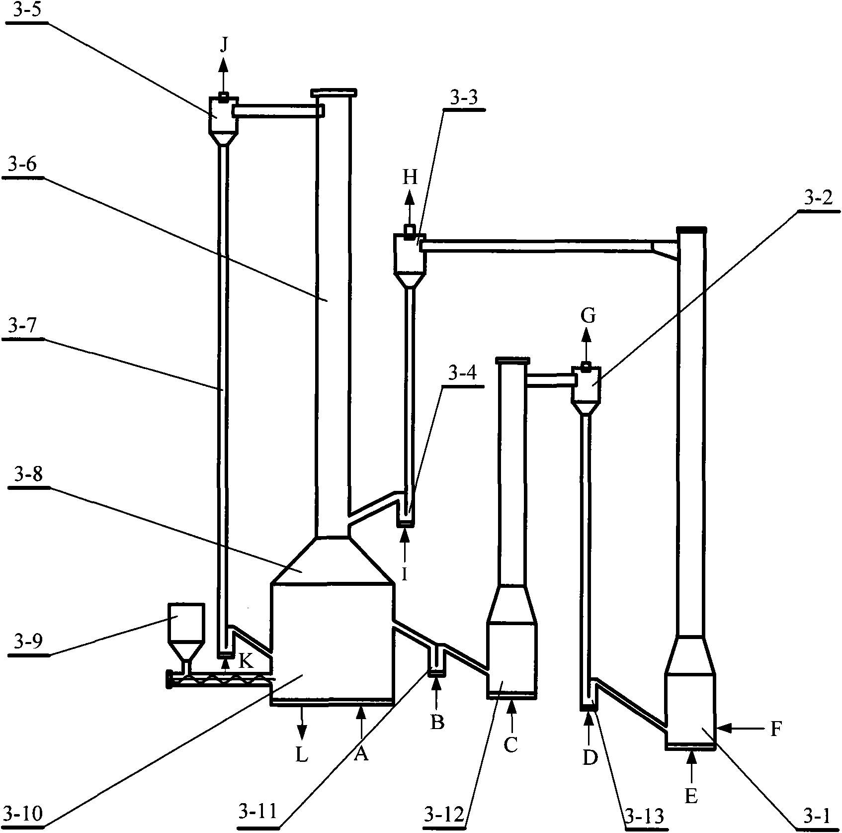
[0065]A chemical looping combustion method utilizing the present invention and using solid fuels, iron or iron oxides are placed in the air reactor 2-1, and fluidizing air is passed into the lower end E of the air reactor 2-1, and the air reactor 2-1 The operating temperature can be controlled at about 800°C to 1250°C, and iron or iron oxides react with oxygen in the air to obtain Fe 2 o 3 , and then the gas-solid two-phase is separated through the air separator 2-3; the separated high-temperature oxygen-poor air is discharged from the upper end H of the air separator 2-3, and is used for power generation or waste heat utilization; the separated Fe 2 o 3 Enter the fuel reactor fluidized bed 2-10 through the feed tank 2-2; the operating temperature of the fuel reactor fluidized bed 2-10 can be controlled at about 800 ° C ~ 1200 ° C; the solid fuel passes through the screw feeder 2-9 Enter the fuel reactor fluidized bed 2-10, the lower end A of the fuel reactor fluidized bed 2...


PUM


Abstract

The invention discloses a fuel reactor device for chemical-looping combustion. The device consists of a mixing and reaction chamber, an overflow groove, a transition section, a riser and a carbon dioxide separator, wherein the riser is connected with the mixing and reaction chamber through the transition section; the lower end of the riser is provided with a feed port, and the upper end of the riser is connected with the upper end of the carbon dioxide separator; the lower end of the carbon dioxide separator is connected with the mixing and reaction chamber through the overflow groove; the lower end of the mixing and reaction chamber is provided with a grid plate; the lower end of the mixing and reaction chamber is provided with a solid fuel inlet; a discharge port is formed on the outer side of the mixing and reaction chamber; and a loose air port is formed at the lower end of the overflow groove. Due to the large change of cross sections of the riser and the mixing and reaction chamber change, and the selection of the position of the feed port, the device has the advantages of improving the oxygen carrying capacity of oxygen carrier and guarantees discharge of clean carbon dioxide in chemical-looping combustion, and solving the problem that clean carbon dioxide cannot be obtained during hydrogenation in chemical-looping hydrogenation.

Description

technical field [0001] The invention relates to a chemical loop combustion fuel reactor device. In particular, it relates to chemical looping combustion fuel reactor devices capable of separating carbon dioxide. Background technique [0002] The problem of global warming caused by greenhouse gas emissions is attracting people's attention. CO 2 As the most important greenhouse gas, the study of CO 2 Emission reduction technologies are imminent. CO in flue gas 2 Often diluted with large amounts of nitrogen, CO 2 The cost of separation and recovery is very high. High concentrations of CO are produced during combustion 2 or facilitate CO 2 It is an effective way to separate the gas phase mixture while eliminating the generation and emission of other pollutants. Chemical loop combustion is a new type of combustion with the above characteristics. The basic principle is to decompose the traditional fuel-air direct contact reaction combustion into two gas-solid reactions wi...

Claims


Application Information

Patent Timeline
Patent Type & Authority Applications(China)
IPC IPC(8): F24J1/00F24V30/00
Inventor 向文国薛志鹏王新
Owner SOUTHEAST UNIV
Why Eureka
Try Eureka