
Fluidizing calciner

A technology of boiling calcination and calcining furnace, which can be used in furnaces, fluidized bed furnaces, furnace types, etc., and can solve the problems of unsatisfactory combustion effect, inconvenient observation and operation, etc.

Inactive Publication Date: 2011-03-30
李竟川 +1
View PDF6 Cites 3 Cited by
  • Summary
  • Abstract
  • Description
  • Claims
  • Application Information

AI Technical Summary

Problems solved by technology

[0010] Although the ebullated bed is a kind of fluidized calcination equipment, which can overcome the shortcomings of the above three calcination furnaces, it still has the disadvantages of unsatisfactory combustion effect and inconvenient observation and operation.

Method used


Image

  • Fluidizing calciner
  • Fluidizing calciner
  • Fluidizing calciner

Examples


Embodiment Construction

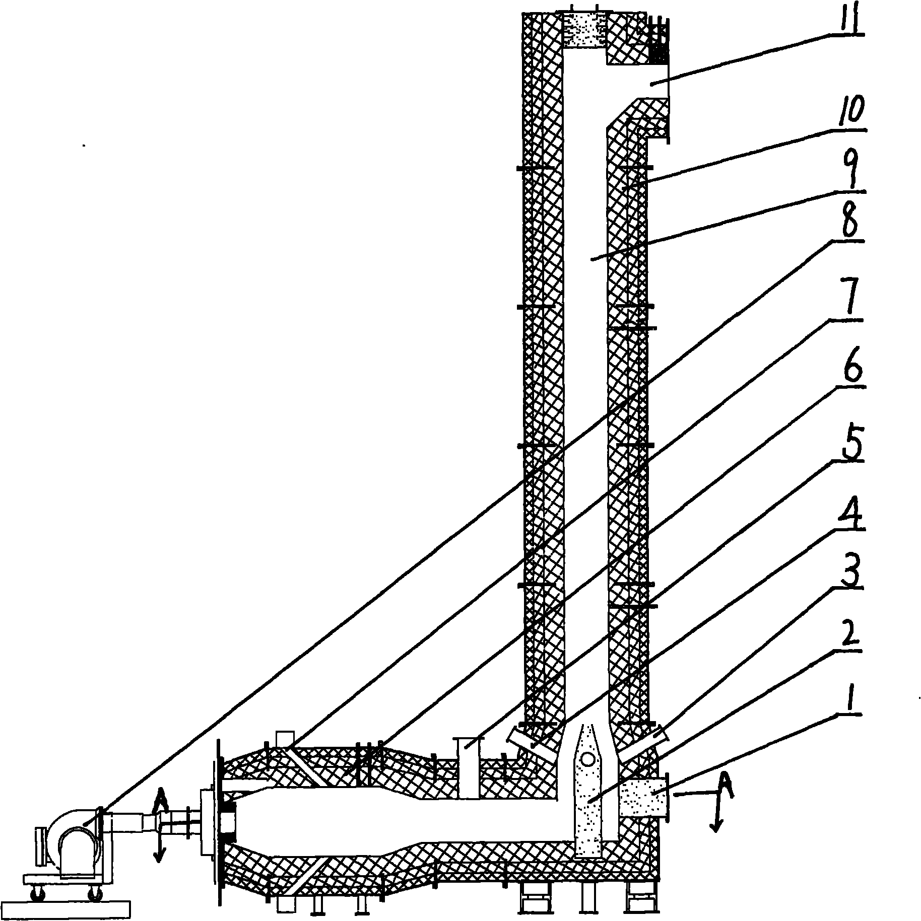
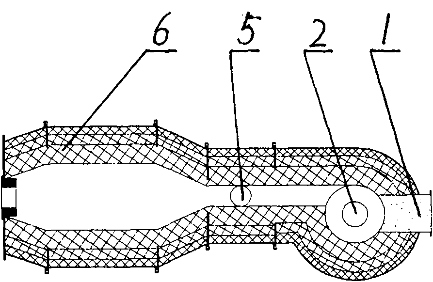
[0019] The present invention includes a calciner 10, the calciner 10 is composed of a combustion chamber 6 and a flue 9 with a discharge port 11 on the side of the combustion chamber 6, the combustion chamber 6 is connected with the burner 8, and the bottom of the flue 9 is a reverse flow Column 2, the side of the backflow column 2 is the backflow port 1, and the wall of the flue 9 above the backflow column 2 is respectively provided with an observation hole 3 and a feed port 4; the tail of the combustion chamber 6 is provided with a high-temperature feeding pipe 5 .

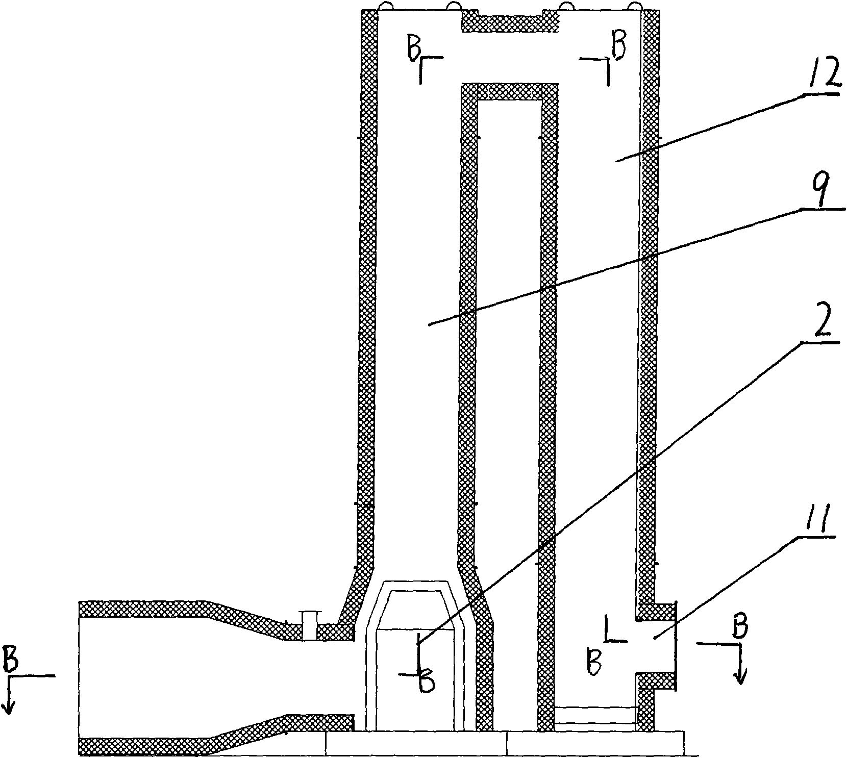
[0020] The discharge port 11 can also be connected with the secondary flue 12, and the bottom of the secondary flue 12 is provided with a discharge port 11. The auxiliary flue 12 can make the material burn more fully.

[0021] A course of action of the present invention is illustrated below in conjunction with accompanying drawing:

[0022] After the material to be calcined is mixed with the high-temperature g...


PUM


Abstract

The invention discloses a fluidizing calciner, which relates to the improvement on the structure of the calciner. The invention provides a fluidizing calciner which allows for easy observation and has excellent calcining effect. The fluidizing calciner comprises a calciner consisting of a combustion chamber and a flue which has a discharge opening and is arranged beside the combustion chamber; the combustion chamber is connected with a combustor; and the bottom of the flue is provided with a backflow column, and a backflow opening is formed beside the backflow column. The structural key points of the fluidizing calciner lie in that: correspondingly, an observation hole and a feeding hole are formed on the flue wall above the backflow column respectively; and the tail part of the combustion chamber is provided with a high-temperature feeding pipe.

Description

Technical field: [0001] The present invention relates to an improvement in the structure of a calciner. Background technique: [0002] Calcination is a chemical process suitable for the improvement, decomposition, purification, oxidation and reduction of inorganic salts. The calcining equipment commonly used now includes rotary kiln, pusher kiln, fixed kiln, fluidized bed and so on. [0003] 1. Rotary kiln: [0004] Rotary kiln is a kind of semi-dynamic calcination equipment widely used in inorganic salt drying. Its main disadvantages are that the operation of the equipment requires huge power, relatively high energy consumption, high daily maintenance costs, serious pollution, and the atmosphere of material calcination. Poor, calcined specific surface area is small; [0005] 2. Pusher kiln: [0006] The pusher kiln is a continuous production calcination equipment, which occupies a large area and takes a long time for calcination. Crucibles are used when calcining mater...

Claims


Application Information

Patent Timeline
Patent Type & Authority Applications(China)
IPC IPC(8): F27B15/00F27B15/02F27B15/08F27B15/09F27B15/14
Inventor 沈丽梅于宗春赵世友万福东
Owner 李竟川
Learn More