
Tightness self-regulating rotating mechanism of bearing performance precision detection instrument

A technology of bearing performance and rotating mechanism, applied in the direction of mechanical bearing testing, etc., can solve the problems of increasing failure rate, complicated connecting device, low detection accuracy, etc., to eliminate the influence of human factors, reduce labor intensity, and improve the effect of detection efficiency.

Inactive Publication Date: 2011-03-30
DALIAN HUAKONG INDAL EQUIP
View PDF0 Cites 4 Cited by
  • Summary
  • Abstract
  • Description
  • Claims
  • Application Information

AI Technical Summary

Problems solved by technology

At present, there are two main ways to rotate the object under test (bearing): one is to rely on manpower and rub it by hand, which will make the rotation speed of the bearing uneven, and it will not be uniform, and the most important thing is that the speed cannot reach Use requirements, low detection accuracy
This approach consumes considerable human resources
The second is driven by a three-phase asynchronous motor. In this way, although the speed can be adjusted and some requirements can be met, the installation is limited, taking up a lot of space, and the connection device will be very complicated.
Increased failure rate in equipment operation

Method used


Image

  • Tightness self-regulating rotating mechanism of bearing performance precision detection instrument
  • Tightness self-regulating rotating mechanism of bearing performance precision detection instrument
  • Tightness self-regulating rotating mechanism of bearing performance precision detection instrument

Examples


Embodiment

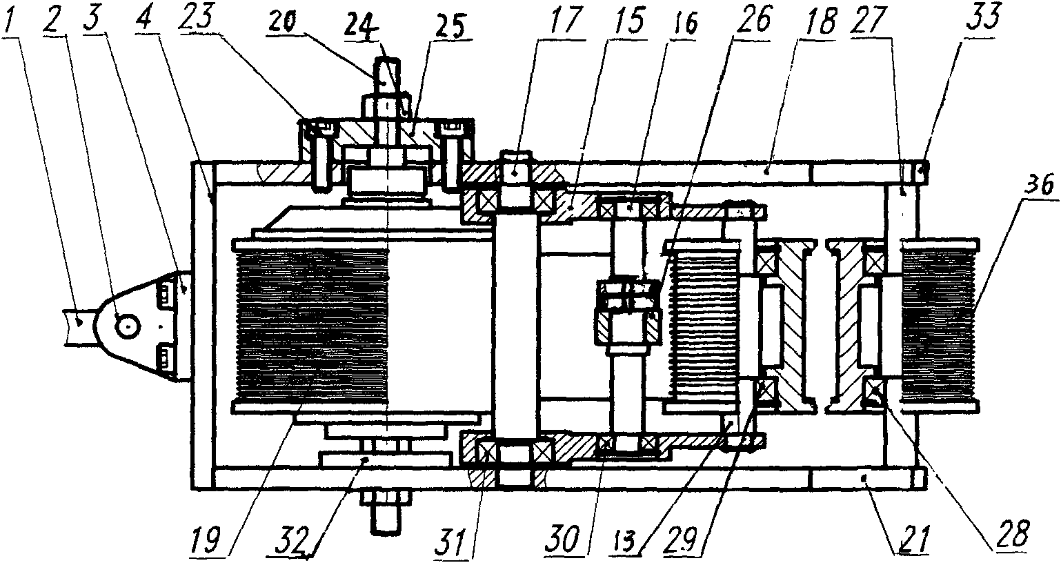
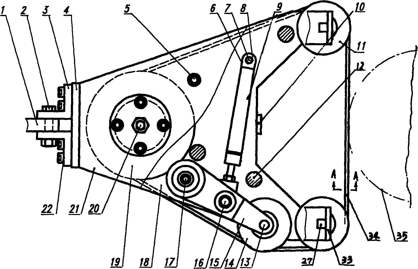
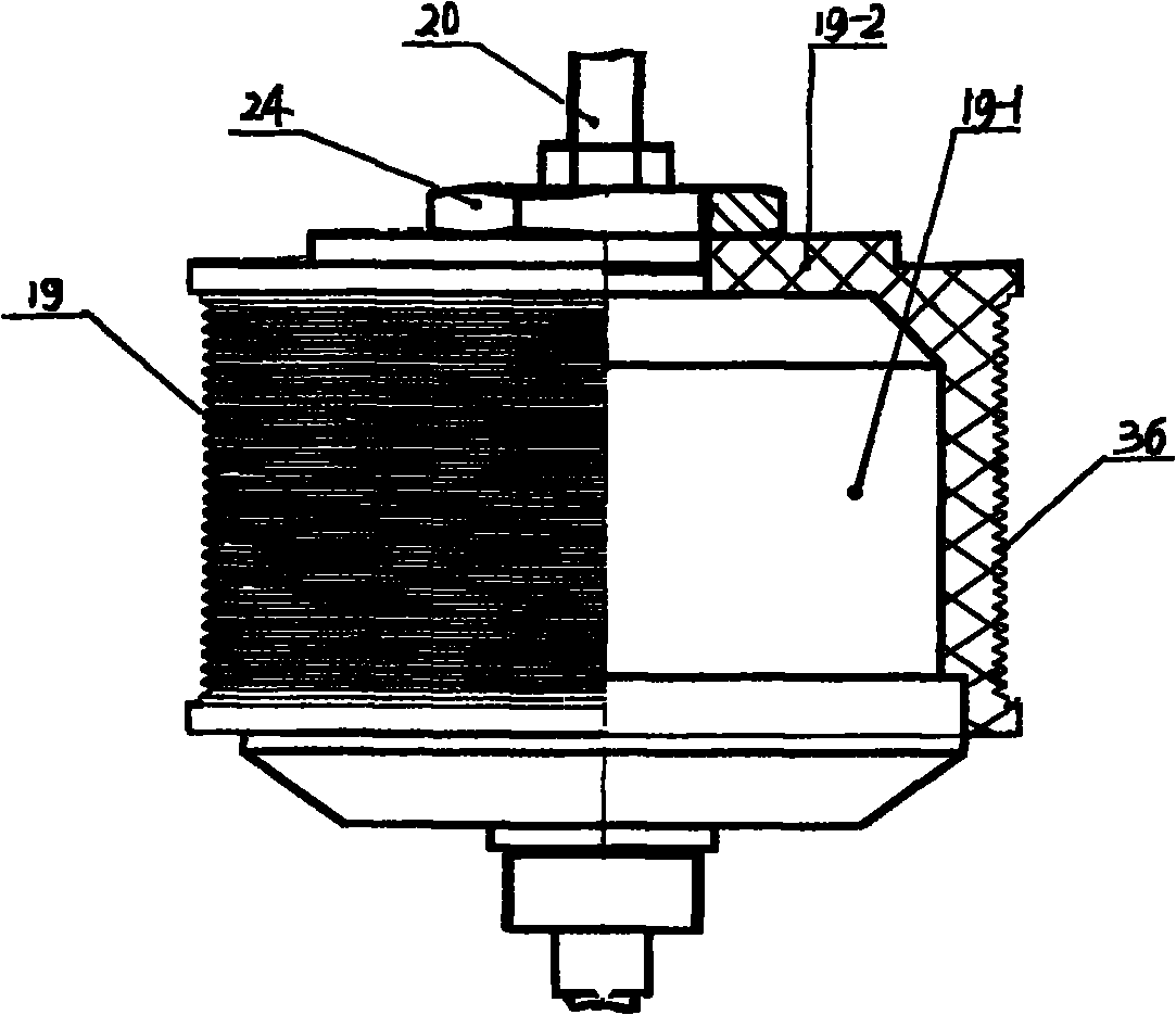
[0013] Embodiment, with reference to the accompanying drawings, a bearing performance precision tester tightness self-adjusting rotating mechanism, including a DC brushless motor 19-1 and a tension gas spring 9, which is characterized in that the DC brushless motor 19-1 and the driving wheel 19 -2 is fixed together, and the driving wheel 19-2 is movably contained on the driving wheel shaft 20, and the driving wheel shaft 20 is fixedly mounted on the left clamping plate 18 and the right clamping plate 21, with three positioning shafts 12 between the left clamping plate 18 and the right clamping plate 21 Connect and locate with a support rod 5, and a positioning plate 10 is housed in the middle, and the left clamping plate 18 and the right clamping plate 21 right end are fixedly equipped with a driven shaft 27 up and down, and a driven wheel is movably equipped with a bearing 28 on the driven shaft 27 11; a centering shaft 17 is also fixedly installed in the left clamping plate 1...


PUM


Abstract

The invention relates to a tightness self-regulating rotating mechanism of a bearing performance precision detection instrument, which comprises a direct current brushless motor 19-1 and a tensioning air spring. The tightness self-regulating rotating mechanism is characterized in that the direct current brushless motor 19-1 and a driving wheel 19-2 are fixed together, the driving wheel 19-2 is movably arranged on a driving wheel shaft 20, the driving wheel shaft 20 is fixedly arranged on a left clamp plate 18 and a right clamp plate 21, the middle sections of the left clamp plate 18 and the right clamp plate 21 are respectively and fixedly provided with a centering shaft 17, two swinging arms 15 are movably arranged on each centering shaft 17 by a fourth bearing 31, a support shaft 16 is movably arranged in the middle of the swinging arms 15 by a third bearing 30, the middle of the support shaft 16 is movably provided with a support rod 26, the support rod 26 is connected with one end of the tensioning air spring 9, the other end of the tensioning air spring 9 is fixed on a fixed air cylinder seat 6, and the fixed air cylinder seat 6 is movably arranged on a fixed air cylinder shaft through a fixed air cylinder sleeve 8. The tightness self-regulating rotating mechanism realizes high-precision detection on the axial play, the assembly height and the end surface jumping of bearings, realizes the rotating kinetic energy required by the detection and can simulate real operation to achieve the full automation of the detection process.

Description

technical field [0001] The invention belongs to a bearing tester, in particular to a tightness self-adjusting rotating mechanism of a bearing performance precision tester. Background technique [0002] The axial clearance of the bearing is one of the key index parameters of the rolling bearing. The so-called internal clearance is the amount of clearance between the outer ring, inner ring and steel ball of the bearing. Generally, when the inner wheel is fixed, the amount of movement when the outer wheel moves up and down is called the radial clearance, and the amount of movement when the outer wheel moves in the left and right directions is called the axial clearance. In the operation of the bearing, the size of the internal clearance is the main factor of performance such as left and right vibration, noise, heat generation, fatigue life and rotation accuracy. The full runout of the end face is a comprehensive reflection of the shape error of the entire end face of the beari...

Claims


Application Information

Patent Timeline
IPC IPC(8): G01M13/04
Inventor 钱志军
Owner DALIAN HUAKONG INDAL EQUIP
Learn More