

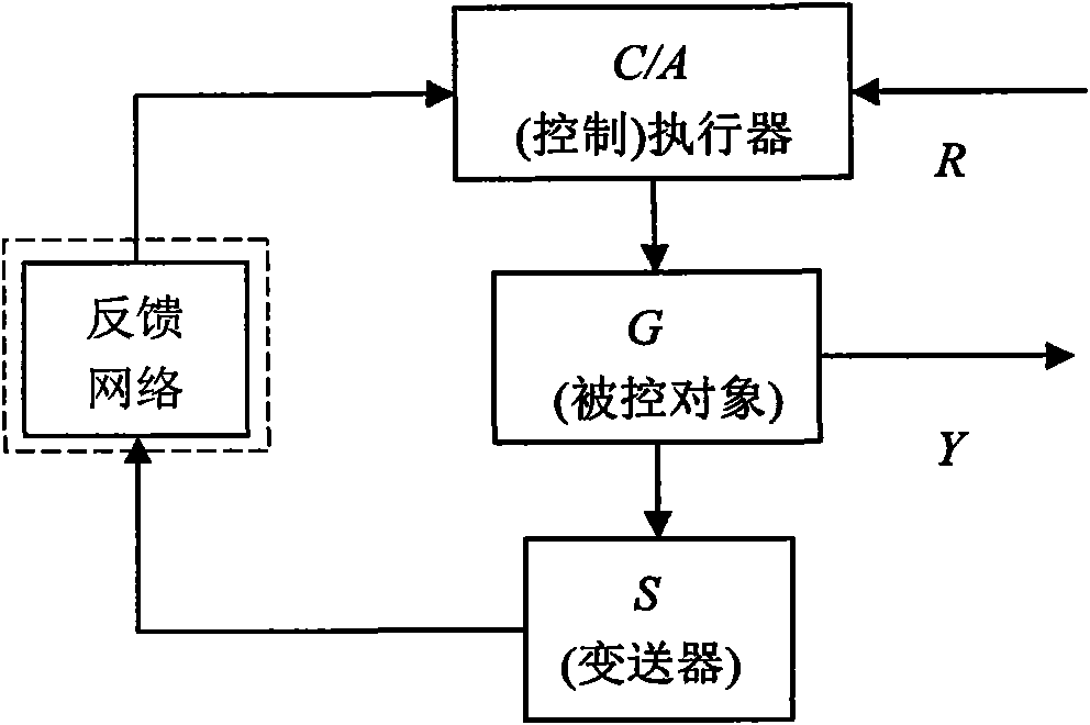
Network delay compensation method between transmitter node and (control) actuator node
A technology of network delay and compensation method, which is applied in the interdisciplinary field of multiple disciplines, can solve problems such as errors in network delay estimation or identification, reduce the impact of delay system stability, large economic investment, etc., to improve control quality, The effect of avoiding node clock signal synchronization and avoiding estimation errors
- Summary
- Abstract
- Description
- Claims
- Application Information
AI Technical Summary
Problems solved by technology
Method used
Image

Examples
Embodiment Construction
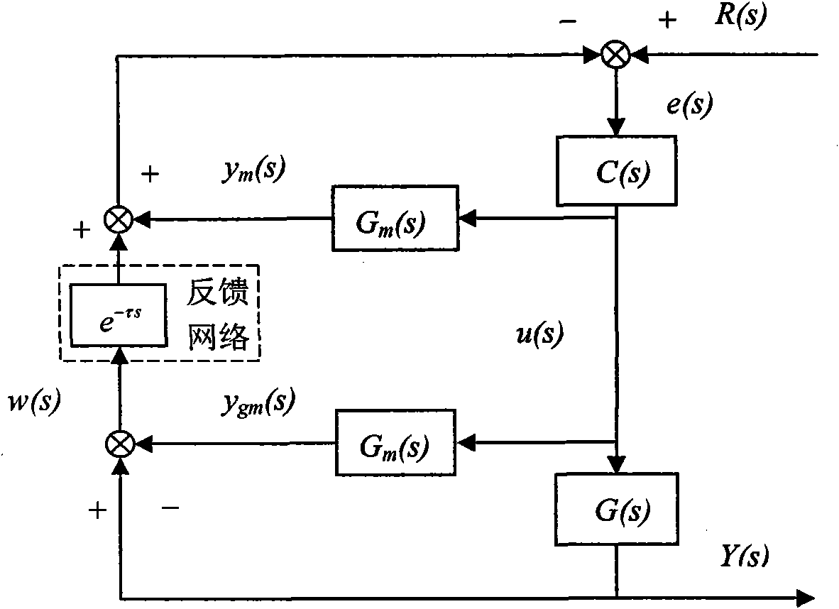
[0069] The following will refer to the attached image 3 Exemplary embodiments of the present invention are described in detail to make the above and other features and advantages of the present invention more apparent to those skilled in the art.
[0070] The specific implementation steps are as follows:
[0071] The first step: the transmitter node working in the time-driven mode outputs the output signal Y(s) of the controlled object G(s) and the output signal y of the controlled object prediction model Gm(s) gm (s) for periodic sampling; for Y(s) and y gm (s) Implement subtraction to obtain the model deviation signal w(s); transmit w(s) to the (control) actuator node through the feedback network path;
[0072] Step 2: The (control) actuator node working in the event-driven mode is triggered by the feedback network path signal w(s); the system given signal R(s) and w(s) and y m (s) Implement the subtraction operation to obtain the error signal e(s); implement the control...
PUM
 Abstract
Description
Claims
Application Information