Supercharge Your Innovation With Domain-Expert AI Agents!

Magnetic group structure of permanent-magnet high-gradient concentrator

A high-gradient, ore concentrator technology, applied in the field of separation, can solve problems such as chemical pollution, unreasonable magnetic group structure, small contact area between ore and magnetic field, etc.

Inactive Publication Date: 2012-05-23
王安生
View PDF0 Cites 0 Cited by
  • Summary
  • Abstract
  • Description
  • Claims
  • Application Information

AI Technical Summary

Problems solved by technology

The permanent magnetic roller concentrator is a magnet arranged on the surface of the roller and the magnetic field strength of the magnetic guide plate can reach 10,000 gauss. It can only sort coarse-grained weak magnetic ore. Due to the unreasonable structure of the magnetic group, the contact area between the ore and the magnetic field is small. , so the recovery rate is low and the grade is poor. In actual production and application, the use of this machine for weakly magnetic ore often needs to be combined with other mineral processing processes to complete. Due to the complex process, many equipment, and large investment, the cost of mineral processing is greatly increased. It will also produce certain chemical pollution during operation, which is difficult to promote

Method used


Image

  • Magnetic group structure of permanent-magnet high-gradient concentrator
  • Magnetic group structure of permanent-magnet high-gradient concentrator
  • Magnetic group structure of permanent-magnet high-gradient concentrator

Examples


Embodiment Construction

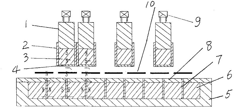
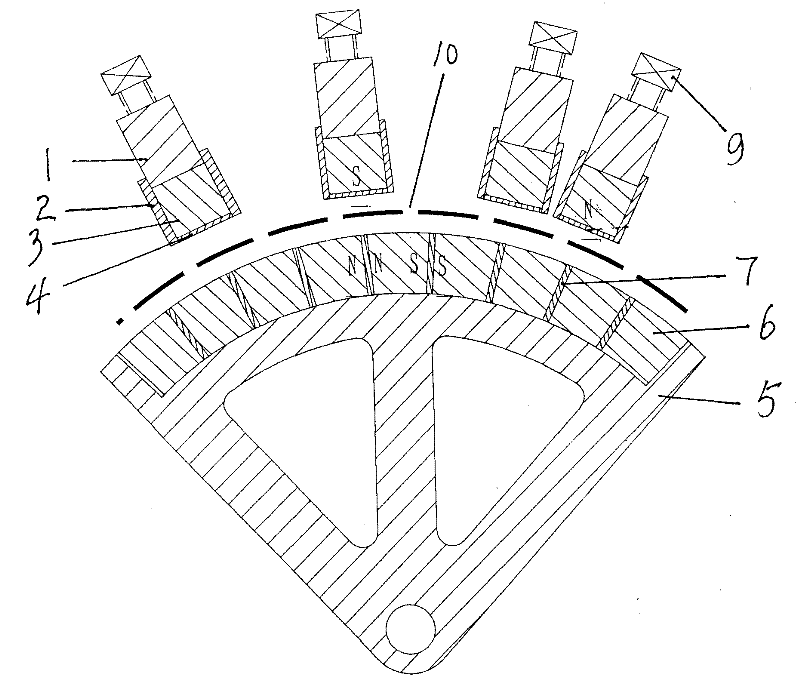
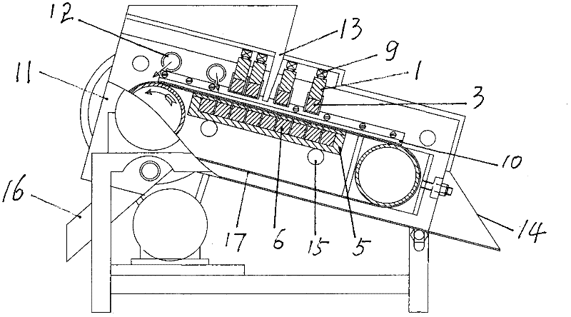
[0009] Embodiments are further described in conjunction with the accompanying drawings. In the present invention, a plurality of magnetic strips are installed side by side on a magnetic strip fixing plate 5, and a plurality of permanent magnets are connected side by side in the same polarity to form a combined permanent magnetic strip 6, and the magnetic poles of each adjacent two permanent magnetic strips are opposite and side by side. Connected into a combined magnetic group, each S-level or N-level combined magnetic pole and the magnetic plate combination lead out a magnetic guide plate 7 upwards, and a magnetic separation channel 10 is left above the magnetic strip fixing plate. A plurality of upper magnet fixing plates 1 are arranged on the top corresponding to each magnetic guide plate, and a combined upper magnetic strip 3 formed by a plurality of permanent magnets arranged in the same polarity is respectively fixed on the bottom of each upper magnet fixing plate, and ea...


PUM


Abstract

The invention discloses a magnetic group structure of a permanent-magnet high-gradient concentrator, comprising a plurality of permanent magnets and a magnetic stripe fixing plate. The magnetic group structure is characterized in that a plurality of permanent magnetic stripes formed by respectively contacting and connecting the same magnetic poles of a plurality of permanent magnets are mounted in parallel on the magnetic stripe fixing plate, magnetic poles between every two adjacent permanent magnet strips are homopolarly and oppositely arranged to form a combined magnetic plate, a magnetism-conducting plate is upwards led out between every two combined magnetic poles, a magnetic separation passage is reserved above the magnetic stripe fixing plate, a plurality of upper magnet fixing plates are arranged above the magnetic separation passage, corresponding to the magnetism-conducting plates, upper magnetic stripes formed by homopolarly arranging and combining a plurality of permanent magnets are respectively fixed at the bottom of the upper magnet fixing plates, the magnetic poles of the combined upper magnetic stripes are opposite to the corresponding magnetic poles of the magnetism-conducting plates, a layer of shielding plates are respectively sealed at the periphery of each upper magnetic stripe, and lifting adjusting screws are respectively mounted at the top of each upper magnet fixing plate. The invention has the advantages of simple structure, high separation efficiency, low cost and easiness for popularization.

Description

Technical field: [0001] The invention relates to separation, in particular to a magnetic group structure suitable for use on a permanent magnet high-gradient ore concentrator. Background technique: [0002] At present, there are a large number of weakly magnetic refractory iron ores and tailings containing weakly magnetic iron ore in my country. The existing magnetic separators include electromagnetic separators and permanent magnetic roller magnetic separators. The electromagnetic field strength of the electromagnetic separator can reach 20,000 Gauss, but due to its beneficiation principle, it cannot meet the beneficiation requirements, and the concentrate grade is low. The permanent magnetic roller concentrator is a magnet arranged on the surface of the roller and the magnetic field strength of the magnetic guide plate can reach 10,000 gauss. It can only sort coarse-grained weak magnetic ore. Due to the unreasonable structure of the magnetic group, the contact area between ...

Claims


Application Information

Patent Timeline
Patent Type & Authority Patents(China)
IPC IPC(8): B03C1/033
Inventor 王安生王良潇
Owner 王安生
Features
  • R&D
  • Intellectual Property
  • Life Sciences
  • Materials
  • Tech Scout
  • Unparalleled Data Quality
  • Higher Quality Content
  • 60% Fewer Hallucinations
Learn More