Rotary cutting tool

A technology of cutting tools and tools, which is applied in the manufacture of tools, drilling accessories, metal processing, etc., can solve the problems of unsatisfactory dimensional accuracy of printed substrates, deterioration of processing surface accuracy, tool breakage, etc., and achieve excellent practicability and good cutting Processing effect

A technology of cutting tools and tools, which is applied in the manufacture of tools, drilling accessories, metal processing, etc., can solve the problems of unsatisfactory dimensional accuracy of printed substrates, deterioration of processing surface accuracy, tool breakage, etc., and achieve excellent practicability and good cutting Processing effect

CN102000863BActive Publication Date: 2012-10-17UNION TOOL

Image

  • Rotary cutting tool
  • Rotary cutting tool
  • Rotary cutting tool

Examples


Embodiment Construction

[0035] The action of the present invention will be shown with reference to the drawings, and preferred embodiments of the present invention will be briefly described.

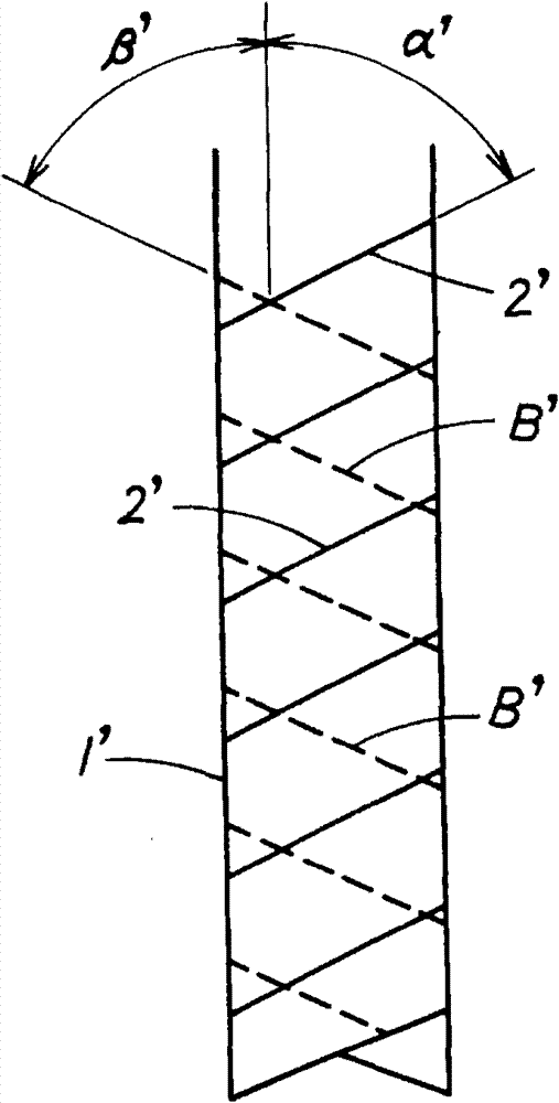
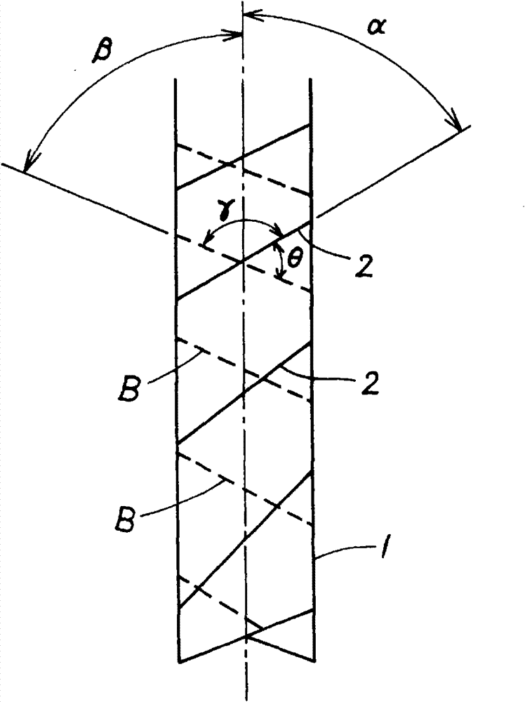
[0036] The workpiece is machined by bringing the tool body 1 into contact with the workpiece while rotating. At this time, since the helix angle α of the outer peripheral cutting edge 2 (flute 3 ) becomes smaller toward the tool end and larger toward the base end, skewing can be suppressed, thereby preventing the outer peripheral edge when the tool is pulled out from the substrate or the like. Chipped cutting edge. In addition, chips are less likely to be jammed on the base end side, and workability and breakage resistance are improved.

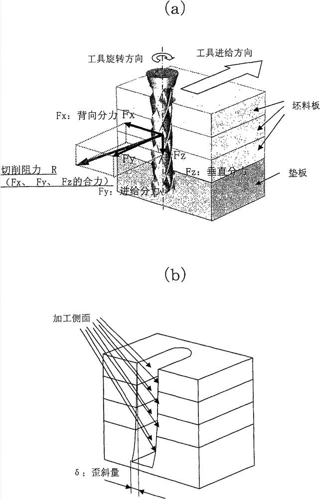
[0037] Specifically, since the helix angle α on the tip side of the tool is small, the skew of the tool body 1 can be suppressed. In particular, the amount of skew δ at the tip of the tool is remarkably small. At this time, the contact between the peripheral cutting edge and...


PUM


Abstract

The invention provides a rotary cutting tool. Compared with a conventional rotary cutting tool with a constant helical angle cuttings chute, the rotary cutting tool keeps good cutting machining for a long distance and has very excellent practicability. A plurality of spiral cuttings chutes (3) towards the proximal end side from the end of the tool are formed on the cirumference of the tool main body (1) and after the front tool surface of the cuttings chute (3) is crossed with the cirumferential surface of the tool main body (1) or the front tool surface of the cuttings chute (3) is crossed with the cirumferential back tool surface formed at the cirumference of the tool main body (1), a cirumferential cutting edge is formed at the crosses edge part and the helical angle (alpha) of the cirumferential cutting edge gradually increases from the end of the tool towards the proximal end side.

Description

technical field [0001] The present invention relates to a rotary cutting tool. Background technique [0002] Generally, a printed circuit board is produced by cutting a green sheet into a plurality of small-sized printed circuit boards of the same specification. For example, it is produced by stacking a plurality of green sheets and processing holes, then performing etching or plating on each of the green sheets to form a pattern, and then performing the above-mentioned processing again on a plurality of sheets. The blank sheets are overlapped, and the blank sheets are cut into small-sized printed substrates of the same specification by using a rotary cutting tool. This cutting process is generally referred to as profile processing. In addition, when performing hole processing or contour processing, a method of overlapping substrates on a backing plate is generally used so that processing can be performed through a predetermined substrate, and the purpose of stacking multi...

Claims


Application Information

Patent Timeline
17 Oct 2012
Publication
CN102000863B
IPC
B23C5/00
CPC
B23B2251/08; B23B2251/24; B26F1/16; B26F2210/08; H05K3/0047
Inventors
佐藤将靖; 高桥宏美