Crystalline silicon ingot furnace thermal field structure with two-stage thermal insulation cage

A heat insulation and heat insulation cage technology, which is applied in the direction of crystal growth, polycrystalline material growth, chemical instruments and methods, etc., can solve the problem of affecting product quality stability, poor product quality stability, unsatisfactory economy and practicability, etc. problems, to achieve thermal field stability and repeatability, not easy to disturb the airflow disturbance, and the system has remarkable energy-saving effect

Inactive Publication Date: 2011-04-06
SHANGHAI CHEN HUA ELECTRIC FURNACE CORP
View PDF9 Cites 7 Cited by
  • Summary
  • Abstract
  • Description
  • Claims
  • Application Information

AI Technical Summary

Problems solved by technology

The shortcoming of this structural heat field is that it needs to heat the entire inner space of the thermal insulation cage during work, which has a large heating space and high energy consumption; when the side thermal insulation cylinder is lifted, a large amount of heat will be lost directly without going through the silicon material, and the heat loss is severe. ; The stability of the thermal field gradient established is poor, which ultimately affects the quality stability of the product; and due to the use of the side insulation cylinder to move up and down, in addition to the corresponding requirement to reserve enough space inside the furnace body, there are also problems with the top insulation board and bottom insulation The gap between the boards is poorly sealed, and it is easy to dissipate heat, which affects the full use of heat
Therefore, the thermal field structure of the existing crystalline silicon ingot furnace generally has disadvantages such as unreasonable structure, high energy consumption during work, low work efficiency, poor product quality stability, etc., which are not ideal from the perspective of economy and practicability.

Method used


Image

  • Crystalline silicon ingot furnace thermal field structure with two-stage thermal insulation cage
  • Crystalline silicon ingot furnace thermal field structure with two-stage thermal insulation cage
  • Crystalline silicon ingot furnace thermal field structure with two-stage thermal insulation cage

Examples


Embodiment Construction

[0016] The present invention will be further described below in conjunction with the accompanying drawings and typical embodiments.

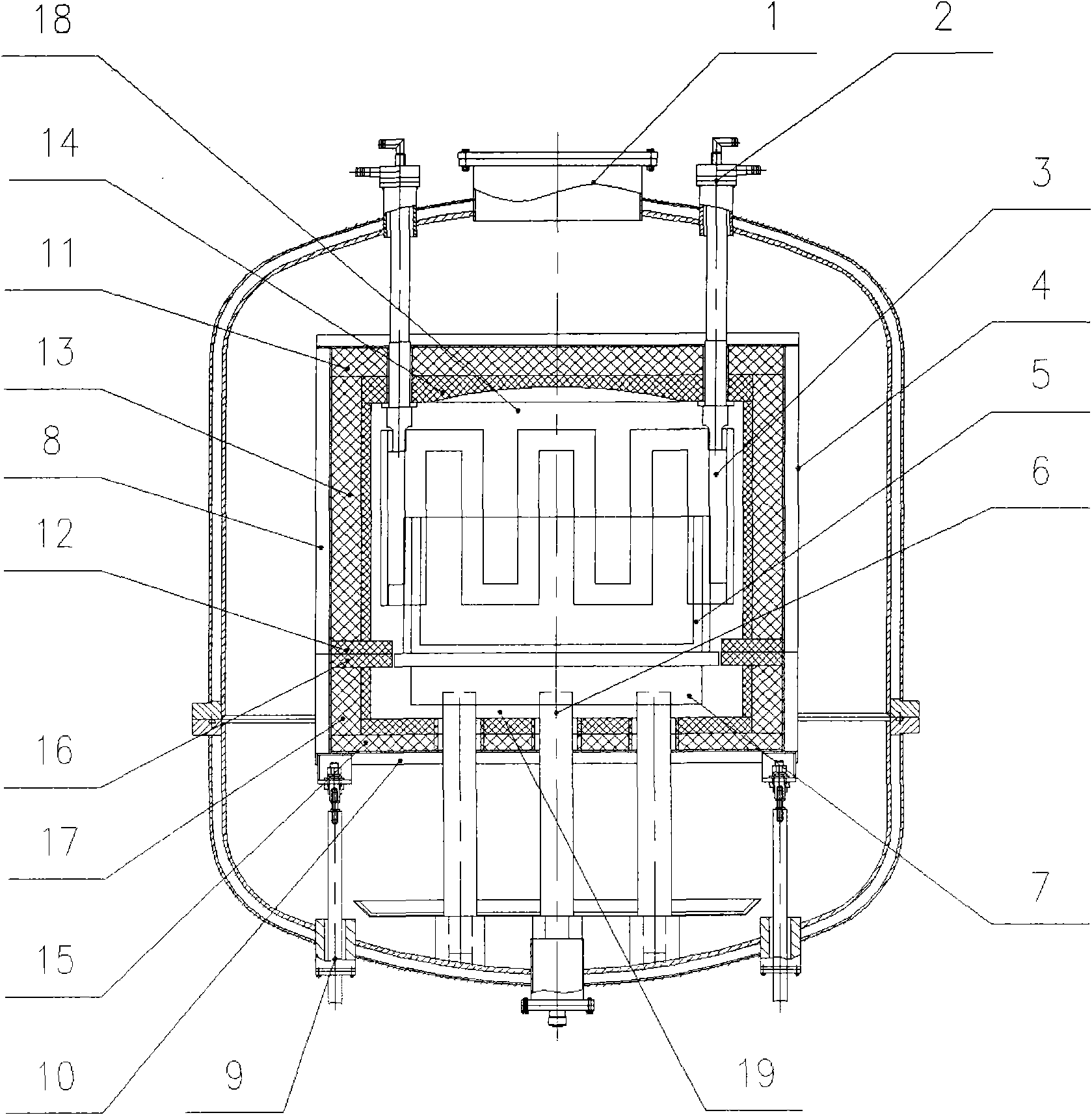
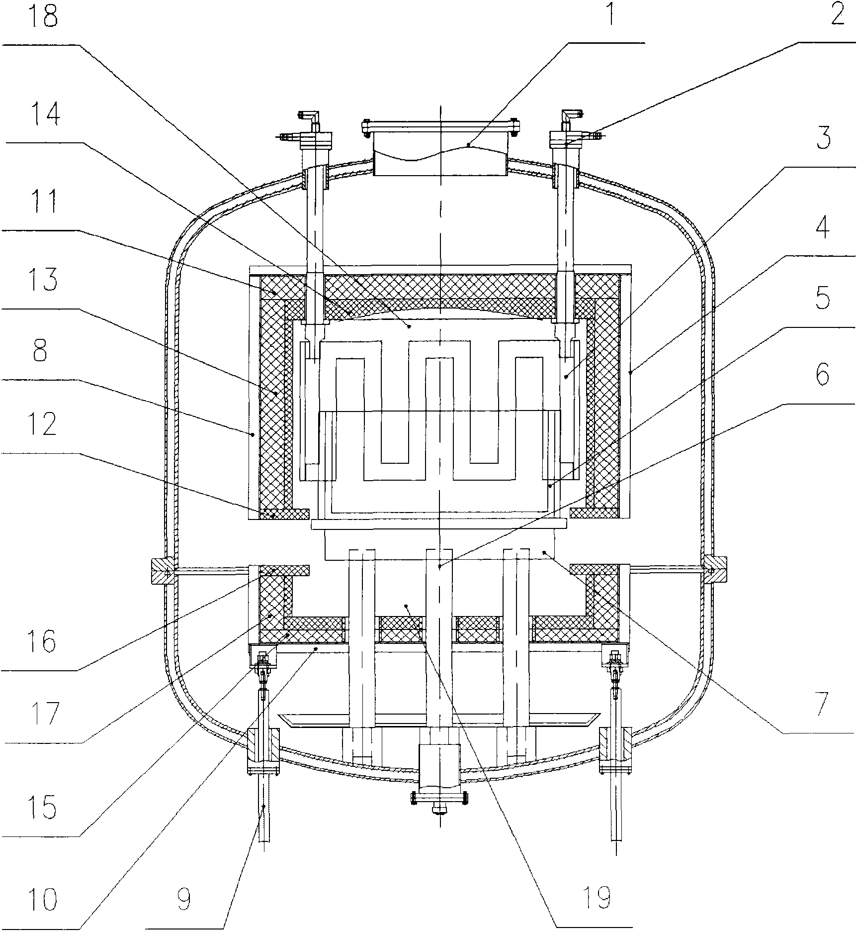
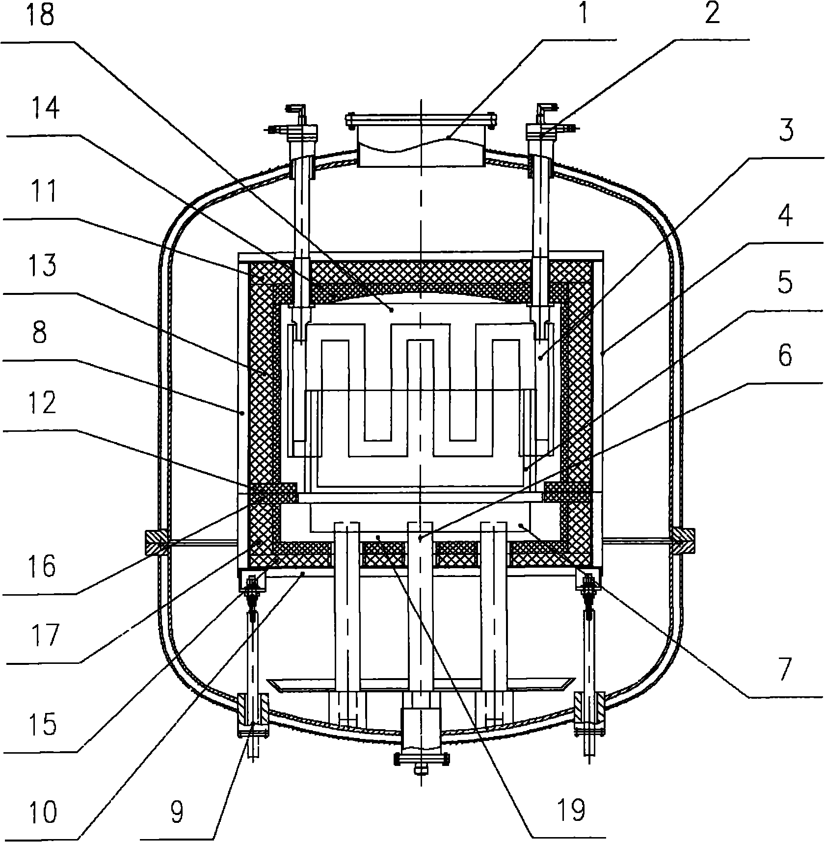
[0017] exist figure 1 with figure 2 Among them, the thermal field structure of the crystalline silicon ingot furnace with a two-stage heat insulation cage of the present invention mainly includes a furnace body 1, a heating element 3 connected to a water-cooled electrode 2, a heat preservation and heat insulation cage 4, and a crucible 54 and The heat exchange table 7 with the lower pillar 6 is characterized in that the thermal insulation cage 4 is a two-stage type, which consists of an upper heat insulation cage 8 fixed on the top of the furnace body and a lower one fixed on the lifting device 9 at the bottom of the furnace body. The heat insulation cage 10 is combined, wherein: the main body of the upper heat insulation cage 8 is an inverted barrel shape, and the top insulation board 11 and the lower edge are provided with an inward-turned L...


PUM


Abstract

The invention relates to a crystalline silicon ingot furnace thermal field structure with a two-stage thermal insulation cage. The thermal insulation cage has a two-stage structure, and consists of an upper thermal insulation cage fixed on the top of the furnace and a lower thermal insulation cage fixed on a lifting device at the bottom of the furnace; the upper thermal insulation cage is an inverted bucket, and consists of a top insulation board and an upper insulation cylinder of which the lower edge is provided with an L-shaped inner-turned upper insulation ring, wherein the top insulation board and the upper insulation cylinder are connected with each other into a whole and the inner surface of the top insulation board is provided with a concave arc reflector; the lower thermal insulation cage is an upright bucket, consists of a bottom insulation board and a lower insulation cylinder of which the upper edge is provided with an L-shaped inner-turned lower insulation ring, and is fixed on the lifting device controlled externally at the bottom of the furnace, wherein the bottom insulation board and the lower insulation cylinder are connected with each other into a whole; and the upper and lower insulating rings separate the inner cavity of the thermal insulation cage into an upper high-temperature area and a lower high-temperature area. The thermal field required by the production of the crystalline silicon is realized by adjusting the lift opening of the lower insulation cage through the lifting device; and the structure has the advantages that: the structure is simple and reasonable and obviously saves energy, the established thermal field has high stability and repeatability, the temperature is difficultly interfered by air disturbance and the structure has high practicability.

Description

technical field [0001] The invention relates to the technical field of manufacturing a crystalline silicon ingot furnace, in particular to a thermal field structure of a crystalline silicon ingot furnace with a two-stage thermal insulation cage. Background technique [0002] With the rapid expansion of the demand for clean and inexhaustible solar energy utilization, the demand for crystalline silicon for solar cells is increasing day by day. However, due to the high production cost of crystalline silicon, the cost of power generation of solar cells remains high. Therefore, it is imperative to reduce the cost of crystalline silicon and improve the quality of crystalline silicon. The key to solving this problem is to design a good thermal field structure of the crystalline silicon ingot furnace to provide a reasonable thermal field for the crystalline silicon ingot. And it can meet the requirements of different thermal fields in different production stages. For example, the me...

Claims


Application Information

Patent Timeline
Patent Type & Authority Applications(China)
IPC IPC(8): C30B28/06C30B29/06
Inventor 廖永建徐炜沈禹张同强孙矿
Owner SHANGHAI CHEN HUA ELECTRIC FURNACE CORP
Why Eureka
Try Eureka