Horizontal screw type headstock gear
A hoist and horizontal screw technology, which is applied in water conservancy projects, sea area projects, coastline protection, etc., can solve the problems of inconvenient manufacturing, storage, transportation, installation, maintenance, limited door opening height, and easy bending of the screw, etc. problems, to achieve the effect of low manufacturing cost, wide application range and extended operating life
- Summary
- Abstract
- Description
- Claims
- Application Information
AI Technical Summary
Problems solved by technology
Method used
Image

Examples
Embodiment Construction
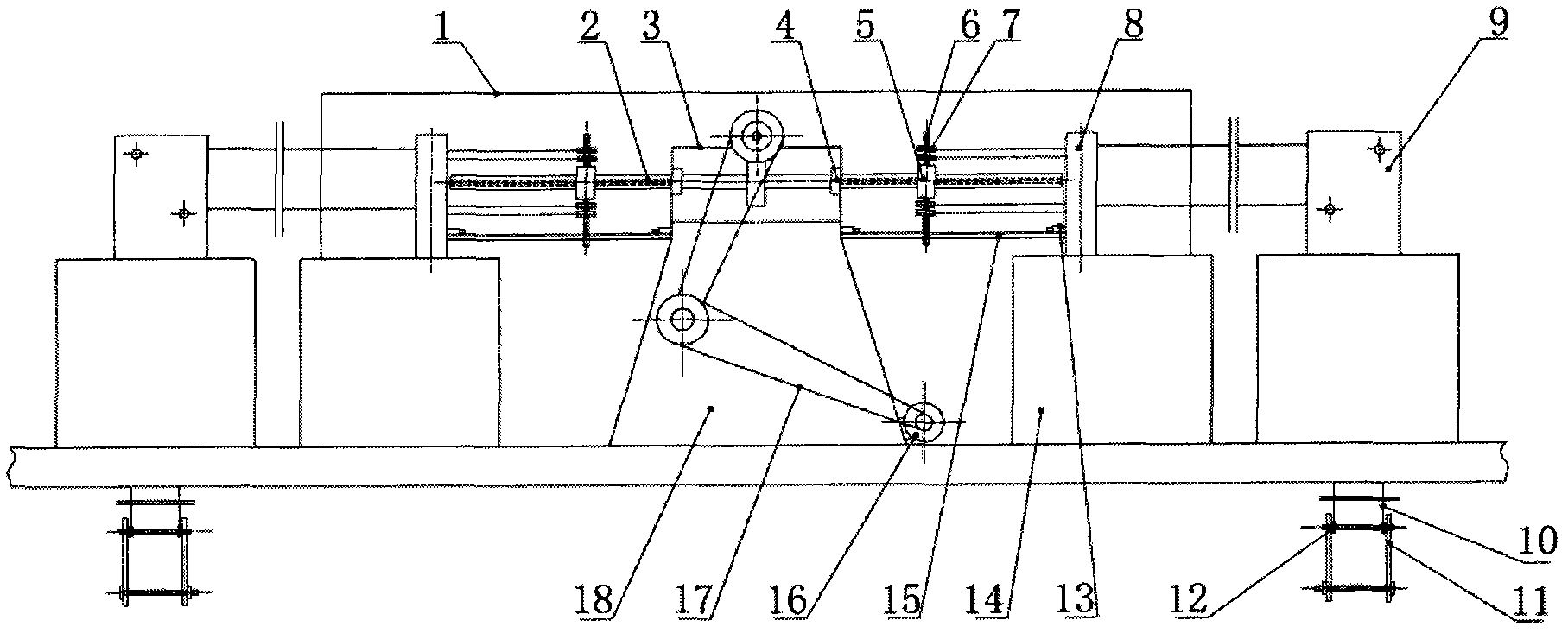
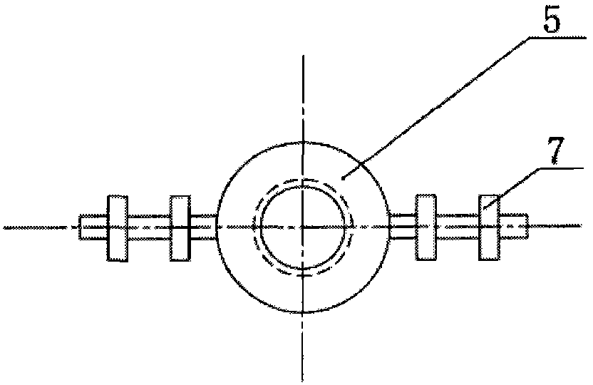
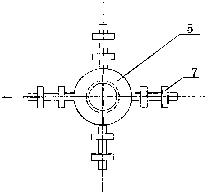
[0014] Accompanying drawing is a kind of specific embodiment of the present invention. The horizontal screw hoist is mainly composed of a power machine, a transmission transmission system, a screw, a nut, a machine base and a hand crank. The screw is driven to rotate by the transmission part. One-body screw 2, that is, two coaxial shafts connected to each other and the thread direction is opposite to the screw. Seat 18 is positioned, is provided with mechanical device on two nuts 5, links to each other with gate by the mechanical facility that cooperates with it and connector. The transmission and speed change parts established on the Siamese leading screw 2 feed rods is a worm gear reducer 3, and the worm gear is vertically arranged, and the Siamese leading screw 2 fixedly connected with it is positioned in the thrust bearing 4 that the worm wheel both sides in the housing are provided with. The mechanical device arranged on the nut 5 is a symmetrically arranged movable pull...
PUM
 Abstract
Description
Claims
Application Information
 - Generate Ideas
- Intellectual Property
- Life Sciences
- Materials
- Tech Scout
- Unparalleled Data Quality
- Higher Quality Content
- 60% Fewer Hallucinations
Browse by: Latest US Patents, China's latest patents, Technical Efficacy Thesaurus, Application Domain, Technology Topic, Popular Technical Reports.
© 2025 PatSnap. All rights reserved.Legal|Privacy policy|Modern Slavery Act Transparency Statement|Sitemap|About US| Contact US: help@patsnap.com