Supercharge Your Innovation With Domain-Expert AI Agents!

Dropped initiation device

A detonating device and drop-in technology, which is applied in the direction of mining fluid, wellbore/well components, earthwork drilling and mining, etc., can solve the problems of lowering safety, misfiring of the detonator, throwing rods and hanging rods, etc., to reduce construction costs, Achieve safe operation and eliminate potential safety hazards

Active Publication Date: 2011-04-06
WUHUA ENERGY TECH CO LTD
View PDF10 Cites 3 Cited by
  • Summary
  • Abstract
  • Description
  • Claims
  • Application Information

AI Technical Summary

Problems solved by technology

Although this traditional perforation method with rod-throwing and detonation has the advantages of simple operation and low perforation cost, it also has the following defects: (1) The rod may hang on the rod during its travel and cannot hit the detonating device. Bring safety hazards to subsequent salvage operations
(2) There is an objective possibility that the detonator misfires. Once it happens, the oil pipe must be raised and the perforator replaced. In addition to delaying the construction period and increasing costs, it also reduces safety
(3) If the perforation pipe string encounters resistance and pier drilling during the process of running down the well, a severe pressure pulse will cause the detonator to fire accidentally, resulting in misperforation accidents
(4) For ultra-high temperature well conditions, since the detonator contains priming charges, its temperature resistance temperature and temperature resistance time are greatly restricted, and it is difficult to use it in ultra-high temperature ultra-deep wells, which limits the impact initiation perforation method scope of application)
(5) For some oil and gas wells with detonation in layers, because the perforator is required to stay in the well for several days, and also due to the restriction of the temperature resistance time of the detonator, the perforation method of percussion detonation cannot be used, and this kind of detonation cannot be used. The superiority of the method

Method used


Image

  • Dropped initiation device
  • Dropped initiation device
  • Dropped initiation device

Examples


Embodiment Construction

[0019] The present invention will be further described in detail below in conjunction with the accompanying drawings and preferred embodiments.

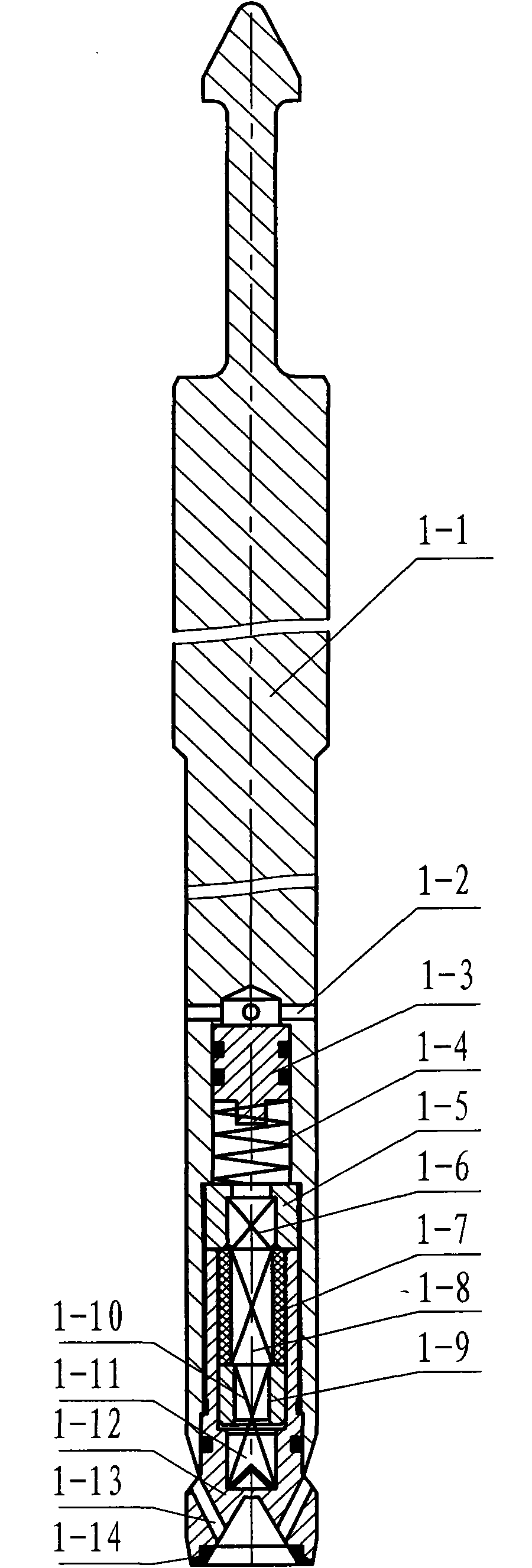
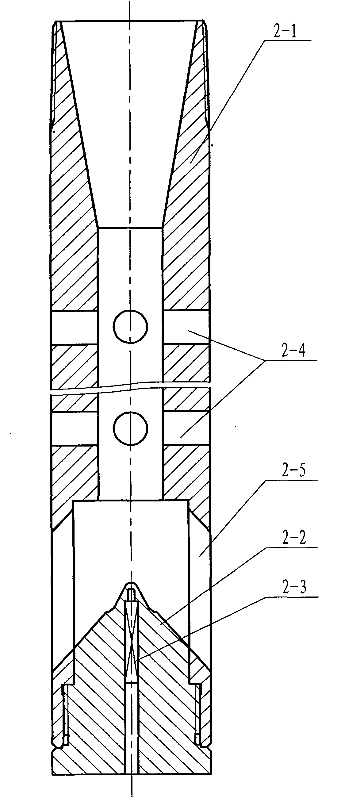
[0020] as figure 1 As shown, the first preferred embodiment of the drop-in detonator of the present invention is composed of a drop-in detonator 1 and an explosion-transfer joint 2. In the non-use state, the drop-in detonator 1 and the explosion-transfer joint 2 are independent.

[0021] according to figure 2 As shown, the delivery detonator 1 includes a rod body 1-1, a delayed firing mechanism, pyrotechnic components, a rod tip 1-11 and a rubber pad 1-12. The upper end of the rod body 1-1 is provided with a fishing head, and the lower end is provided with a first blind hole along the axis. The first blind hole is a two-step stepped hole. The outermost hole of the first blind hole is provided with a female thread. The first blind hole The minimum hole at the bottom of the bottom is provided with a plurality of inlet pressure passa...


PUM


Abstract

The invention discloses a dropped initiation device which is suitable for impacted initiation perforating operation transmitted by oil pipes of an oil well. The device consists of a dropped primer and a transmission detonation joint which are independent to each other; the dropped primer consists of a rod body and a rod point which are in screw connection, and a delay firing mechanism and priming system components which are arranged in the rod body and the rod point; the transmission detonation joint is composed of a guide sleeve and a gun joint which are in screw connection, and a booster which is arranged in the gun joint. When in perforating operation, the upper end and the lower end of the transmission detonation joint are respectively connected with the oil tube and a perforating gun; when the transmission detonation joint drops into a destination layer in the well and the dropped primer is dropped to the destination along the oil tube, a cone boss at the upper end of the gun joint is located in a V-shaped hollowness at the lower end of the rod point; after a certain delay, the delay firing mechanism fires the priming system components to output a high speed jet flow; the high speed jet flow passes through the outer wall of the rod point and the gun joint, and then ignites the transmission detonation joint, thereby igniting perforating bullets and finishing the perforating operation. The device is safe, reliable and low in cost.

Description

technical field [0001] The invention belongs to the field of oil and gas well tubing transmission perforation operations, and mainly relates to a detonation device, in particular to a drop-in detonation device. Background technique [0002] Rod impact initiation perforation is an important initiation method in tubing transmission (TCP) perforation operation in oil and gas wells. During the perforating operation with rods, generally the detonating device is directly connected to the perforation construction pipe string, and then lowered into the construction well together with the construction pipe string. Detonating device. Although this traditional perforation method with rod-throwing and detonation has the advantages of simple operation and low perforation cost, it also has the following defects: (1) The rod may hang on the rod during its travel and cannot hit the detonating device. Bring safety hazards to follow-up salvage operations. (2) There is an objective possibil...

Claims


Application Information

Patent Timeline
IPC IPC(8): E21B43/116E21B43/1185
Inventor 肖勇李静岑章松桥魏领王峰李哲雨彭加斌门媛媛
Owner WUHUA ENERGY TECH CO LTD
Features
  • R&D
  • Intellectual Property
  • Life Sciences
  • Materials
  • Tech Scout
  • Unparalleled Data Quality
  • Higher Quality Content
  • 60% Fewer Hallucinations
Learn More