
Detachment-free oil drainage bolt

A technology of oil drain bolts and oil drain pipes, which is applied in the direction of adding/discharging lubricants and lubricating parts, etc., can solve the problems of pollution, failure to achieve functions, reduction of oil viscosity, etc., and achieve the effect of reducing pollution and avoiding splashing.

Active Publication Date: 2011-04-06
铜陵市世纪朝阳数码科技有限责任公司
View PDF5 Cites 22 Cited by
  • Summary
  • Abstract
  • Description
  • Claims
  • Application Information

AI Technical Summary

Problems solved by technology

[0003] When the engine is working, under high temperature, high speed, high speed and irregular changes, metal debris generated by the friction of various parts, dust intruded from the air, acidic substances generated by combustion, and some fuel that has not been completely burned are mixed into the engine oil, making the engine oil Viscosity decreases; part of the exhaust gas from the combustion chamber enters the crankcase and brings in components such as acid anhydride to deteriorate the engine oil, making it unable to achieve its proper function, which will affect the working efficiency and life of the engine. Therefore, after a certain mileage, the engine oil must be replace
[0004] When changing the engine oil, it is necessary to place a waste oil container under the oil pan, slowly unscrew the oil drain bolt, and the waste oil will flow out from the oil drain hole. During the above process, the waste oil is easy to splash and cause pollution

Method used


Image

  • Detachment-free oil drainage bolt
  • Detachment-free oil drainage bolt
  • Detachment-free oil drainage bolt

Examples


Embodiment Construction

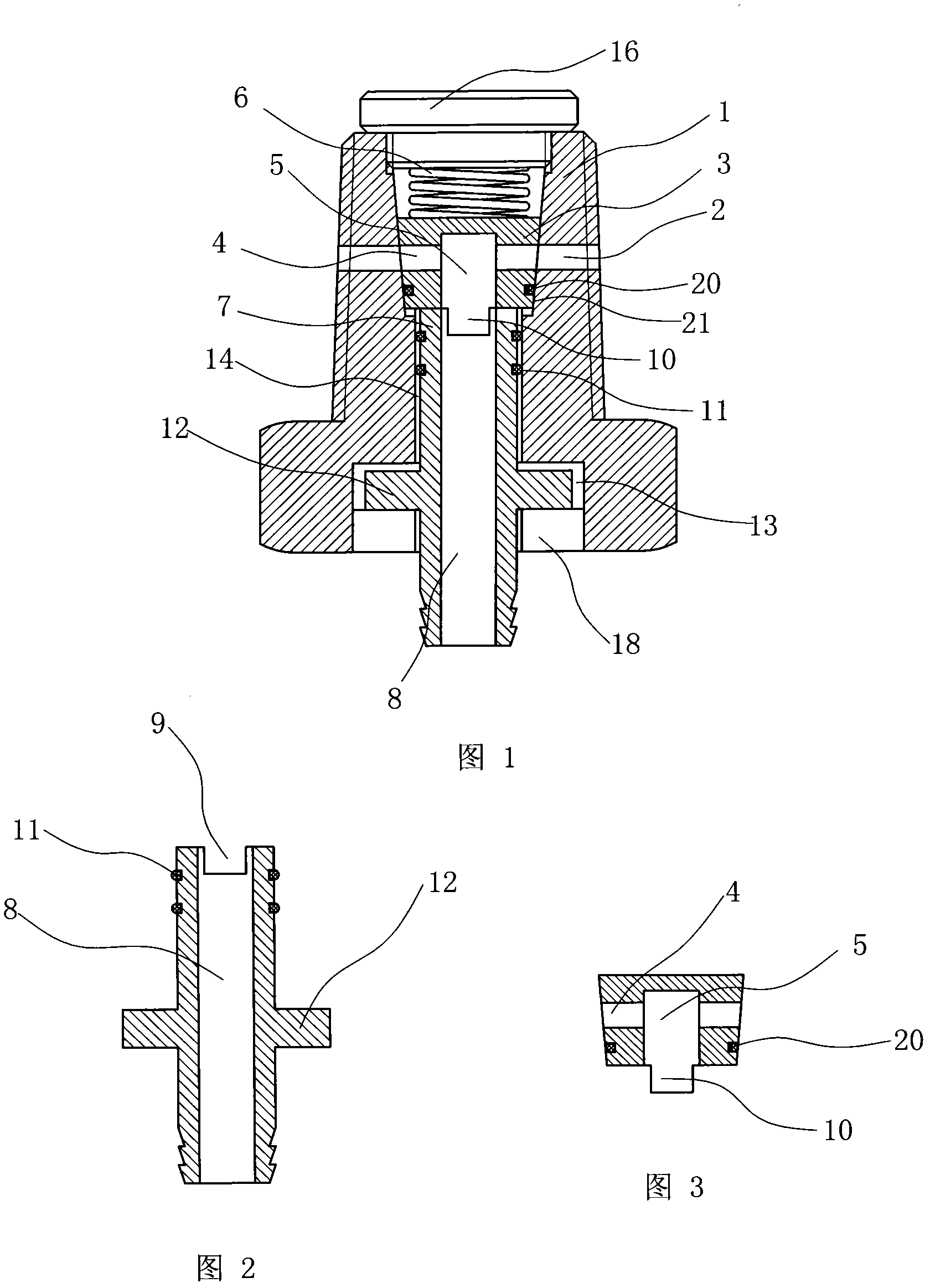
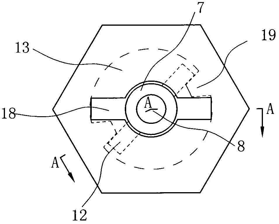
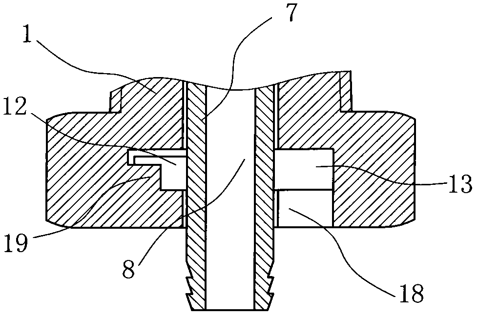
[0035] Such as figure 1 , figure 2 ,and image 3 As shown, the oil discharge bolt is not required to be disassembled, including: a valve body 1, which doubles as an oil discharge bolt, and the valve body 1 is provided with an external thread connecting the oil pan, and the valve body 1 is provided with a The valve body oil inlet hole 2 communicated with the inner cavity of the shell, the valve body 1 is also provided with the valve body oil outlet hole 14 communicated with the outside of the oil pan; the cock spool 3 is installed on the valve body 1 Inner cavity, the cock spool 3 is provided with a spool oil inlet channel 4 corresponding to the valve body oil inlet hole 2, and the cock spool 3 is also provided with a spool oil outlet channel 5, so The spool oil inlet channel 4 is connected with the spool oil outlet channel 5, and the spool oil outlet channel 5 is connected with the valve body oil outlet hole 14; the cock spool 3 is connected with the valve body A spool sea...


PUM


Abstract

The invention discloses a detachment-free oil drainage bolt, which comprises a valve body, a plug valve core and an oil drainage device. The valve body also serves as an oil drainage bolt and is provided with an external thread, a valve body oil inlet and a valve body oil outlet; the plug valve core is mounted in an inner cavity of the valve body and provided with a valve core oil inlet channel; a valve core oil outlet channel communicated with the valve core oil inlet channel is also arranged in the plug valve core; the valve core oil outlet channel is communicated with the valve body oil outlet; a valve core sealing device is arranged between the plug valve core and the valve body; the oil drainage device comprises an oil drainage pipe inserted into the valve body oil outlet; the oil drainage pipe is provided with an oil drainage channel communicated with the valve core oil outlet channel; a valve core opening device is arranged between the oil drainage pipe and the plug valve core;and an oil drainage pipe inserting / fixing device is also arranged between the oil drainage pipe and the valve body. The oil drainage pipe drives the plug valve core to rotate through the valve core opening device, the valve body oil inlet is opened, and the waste oil enters the valve core oil outlet channel through the valve core oil inlet channel from the valve body oil inlet and then flows out through the oil drainage pipe. Through the invention, the waste oil is prevented from spattering around, and the pollution is reduced.

Description

technical field [0001] The invention relates to an oil drain bolt. Background technique [0002] The main functions of engine oil include: lubrication, sealing, heat dissipation and rust prevention. The condition of the engine oil directly affects the performance and life of the engine, so it must be replaced in time. [0003] When the engine is working, under high temperature, high speed, high speed and irregular changes, metal debris generated by the friction of various parts, dust intruded from the air, acidic substances generated by combustion, and some fuel that has not been completely burned are mixed into the engine oil, making the engine oil Viscosity decreases; part of the exhaust gas from the combustion chamber enters the crankcase and brings in components such as acid anhydride to deteriorate the engine oil, making it unable to achieve its proper function, which will affect the working efficiency and life of the engine. Therefore, after a certain mileage, the eng...

Claims


Application Information

Patent Timeline
Patent Type & Authority Applications(China)
IPC IPC(8): F01M11/04
Inventor 郑成龙
Owner 铜陵市世纪朝阳数码科技有限责任公司
Learn More