
Pressure-converging internal circulation multi-fuel engine

An internal circulation and engine technology, applied to internal combustion piston engines, combustion engines, engine components, etc., can solve the problems of internal combustion engines that cannot burn, pollute the environment, and limit the use of fuel

Inactive Publication Date: 2011-04-06
范明合
View PDF0 Cites 0 Cited by
  • Summary
  • Abstract
  • Description
  • Claims
  • Application Information

AI Technical Summary

Problems solved by technology

[0002] At present, in the era when biogas, liquefied petroleum gas and various solid fuels coexist in large quantities, only fuel oil and natural gas are used as fuels for internal combustion engines, which limits the scope of use of fuels, especially the vigorous development of rural biogas, which many farmers use in summer. The waste of biogas not only wastes fuel resources but also pollutes the environment. The existing internal combustion engines cannot burn such gas and solid fuels. This kind of scattered and wide-ranging fuel resources can be used as a good clean energy for power generation.

Method used


Image

  • Pressure-converging internal circulation multi-fuel engine
  • Pressure-converging internal circulation multi-fuel engine
  • Pressure-converging internal circulation multi-fuel engine

Examples


Embodiment Construction

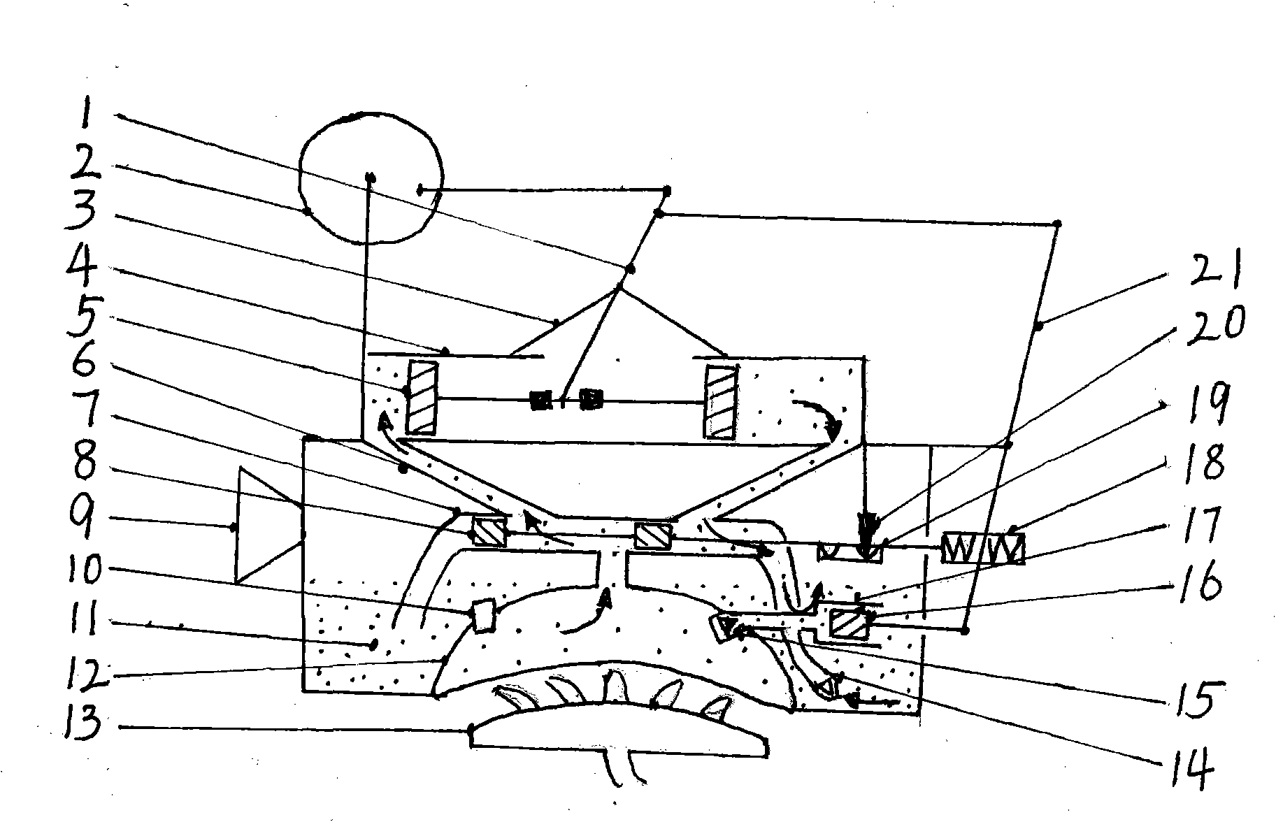
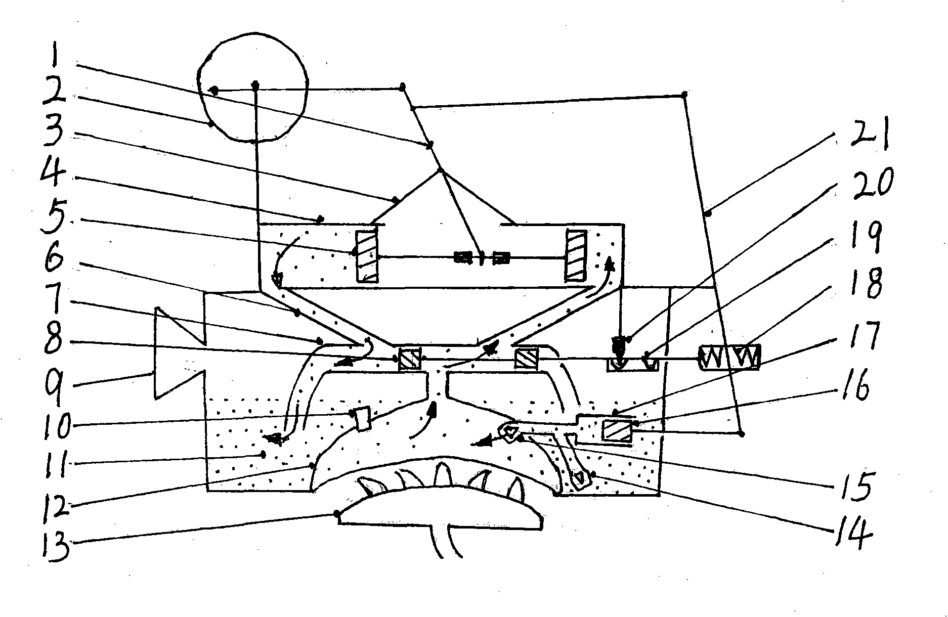
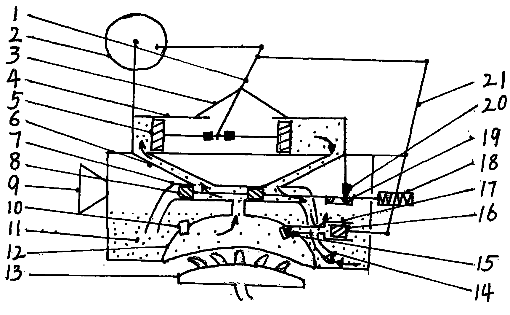
[0009] exist figure 1 In the process, make a pressure-gathering evaporation chamber (12) with a large heating bottom area and a small memory space. A pressure-stabilizing valve (10) is installed on the pressure-gathering evaporation chamber (12), and the steam outlet at the upper end of the pressure-gathering evaporation chamber (12) is connected. Valve sleeve (7) center hole, there is a left hole and a right hole respectively on the opposite side of movable valve sleeve (7) center hole. Connect the right side in the cylinder liner (4) with a steam pipe, connect the two small pistons (8) of the movable valve with a connecting rod and put them into the movable valve sleeve (7), and the central hole of the movable valve sleeve (7) is always on the Between the two small pistons (8), the two small pistons (8) of the movable valve can only lead to the center hole and the left hole when they are in the left position, and they can only lead to the center hole and the right hole when ...


PUM


Abstract

The invention relates to a pressure-converging internal circulation multi-fuel engine which has small volume and wide fuel range, and especially can use rural methane and solid fuel. A pressure-converging evaporating chamber has small internal storage space and large heating surface, and realizes quick ignition without idle start-up; a top steam outlet pipe of the pressure-converging evaporating chamber is communicated with a center hole of a movable valve sleeve; a left hole and a right hole at the opposite sides of the center hole are communicated with the left side and the right side of a cylinder sleeve through steam pipes; when two small pistons of a movable valve are in a left position or a right position, the center hole can be communicated with one of the left hole and the right hole; an oblong opening is arranged in the middle of the cylinder sleeve; the two pistons are put into the cylinder sleeve and connected by connecting rods; a rocker arm is installed on a fulcrum; the lower end of the rocker arm is between two blocking pieces of the piston connecting rods; the upper end of a pendulum rod is connected with the upper end of the rocker arm; a hollow damping part is installed on the right connecting rod of the two small pistons of the movable valve; a frame is arranged at the right end of the connecting rod; two springs are installed in the frame; the lower part of the pendulum rod is between the two springs; a one-way outlet valve is installed on a guide pipe of a plunger sleeve and communicated with the pressure-converging evaporating chamber; another guide pipe is inserted into an inner pipe orifice of circulating liquid and provided with a one-way inlet valve; and a plunger tappet is connected with the lower end of the pendulum rod.

Description

1. Technical field [0001] The invention relates to an engine, especially a multi-combustion engine with accumulating pressure and internal circulation that can burn multiple fuels and can start quickly. 2. Background technology [0002] At present, in the era when biogas, liquefied petroleum gas and various solid fuels coexist in large quantities, only fuel oil and natural gas are used as fuels for internal combustion engines, which limits the scope of use of fuels, especially the vigorous development of rural biogas, which many farmers use in summer. The waste of biogas not only wastes fuel resources but also pollutes the environment. The existing internal combustion engines cannot burn such gas and solid fuels. This kind of scattered and wide-ranging fuel resources can be used as a good clean energy for power generation. 3. Contents of the invention [0003] The content of the present invention is to provide a multi-combustion engine with accumulating pressure internal c...

Claims


Application Information

Patent Timeline
IPC IPC(8): F02B43/10F02B75/28F02M21/02
CPCY02T10/32Y02T10/30
Inventor 范明合
Owner 范明合
Learn More