
Particle engine

An engine and particle technology, applied in machines/engines, jet propulsion devices, etc., can solve problems such as insufficient understanding of atomic structure, inability to use nuclear power, radioactive pollution, etc., and achieve the effect of light weight, simple structure, and large jet thrust

Inactive Publication Date: 2011-04-06
陈久斌
View PDF0 Cites 0 Cited by
  • Summary
  • Abstract
  • Description
  • Claims
  • Application Information

AI Technical Summary

Problems solved by technology

[0002] Existing engines, mainly internal combustion engines and jet engines, cannot use nuclear power
The existing mass-energy reaction that converts matter into energy cannot be artificially controlled to use nuclear fusion reaction, nuclear fission reaction can only use heavy elements as nuclear fuel, there are problems such as radioactive pollution, nuclear waste, nuclear safety, etc.
The understanding and utilization of mass-energy reactions in existing technologies have just started, and the understanding of the structure of atoms is not comprehensive enough

Method used


Image

  • Particle engine
  • Particle engine
  • Particle engine

Examples


Embodiment Construction

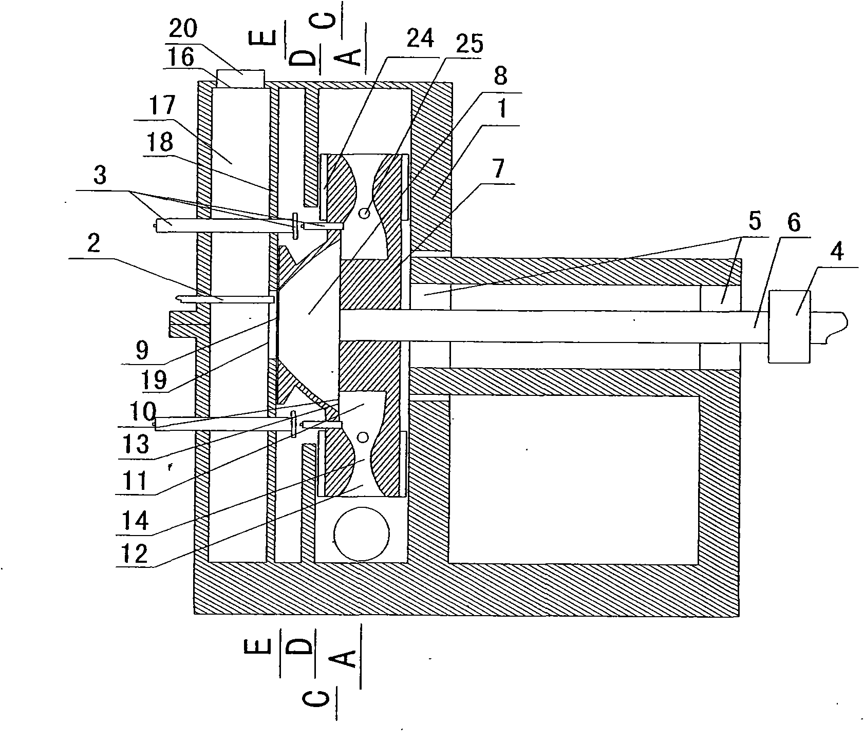
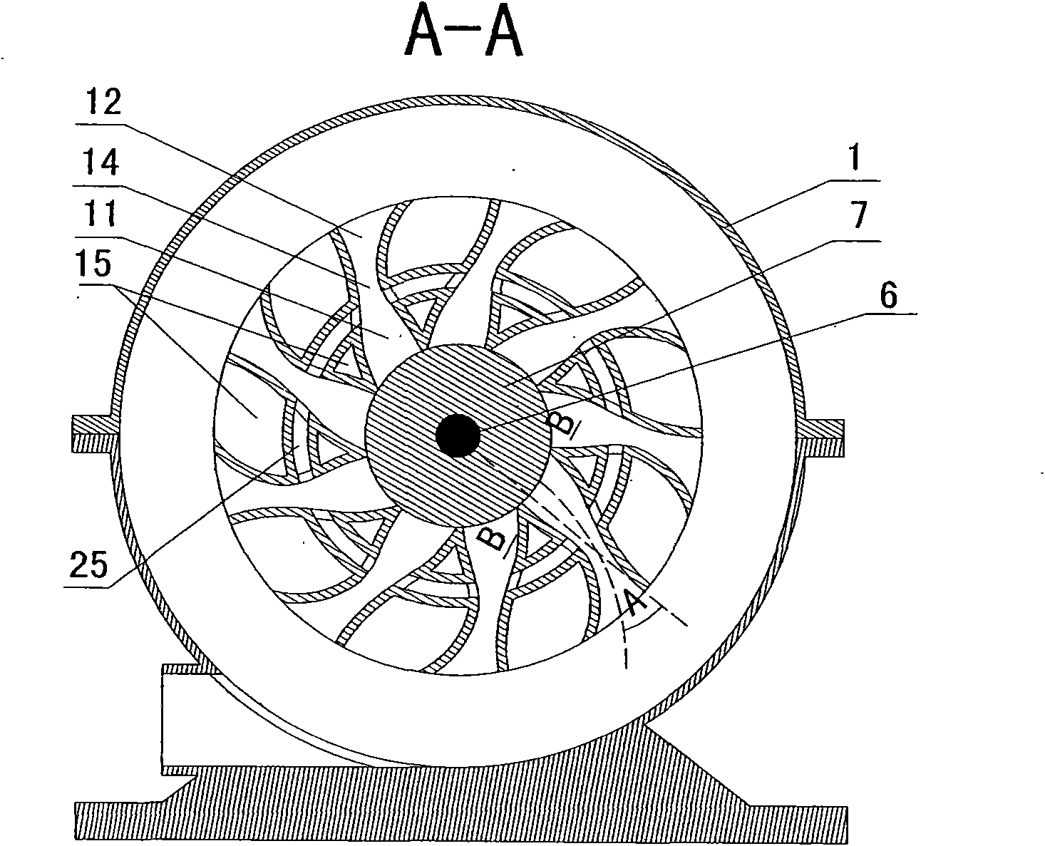
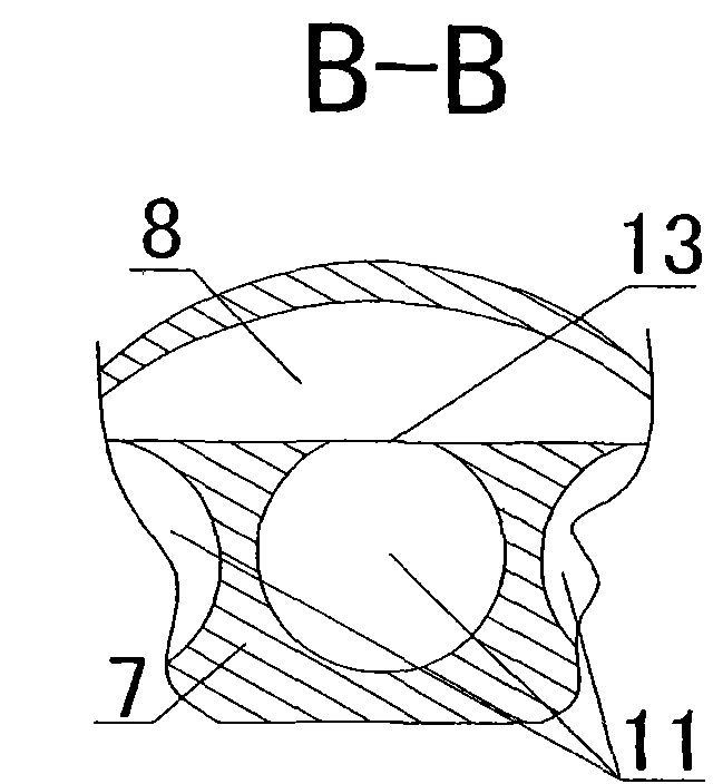
[0023] The main structure of the present invention is: a particle engine, including a housing 1, a starting system 2, a fuel system 3 and an ignition system 4, the housing 1 is installed with a flywheel shaft 6 through a rotating device 5, the flywheel shaft 6 is connected to the starting system 2, and the flywheel shaft 6 The flywheel 7 is installed on the flywheel 7, and the vortex chamber 8 is arranged on the flywheel 7. The vortex chamber air inlet 9 is provided in the axial center area of ​​the vortex chamber 8, and the fuel system 3 and the air intake control device 18 are arranged corresponding to the vortex chamber air inlet 9. The axial cross section of the vortex chamber 8 A plurality of vortex chamber air outlets 10 are arranged on the periphery of the inner wall, and a plurality of reaction chambers 11 and jet chambers 12 are arranged on the periphery of the flywheel 7. The ignition system 4 is arranged corresponding to the reaction chamber 11, and the reaction chamb...


PUM


Abstract

The invention provides a particle engine which comprises a shell, a starting system, a fuel system and an ignition system, wherein, the shell is provided with a flywheel shaft through a rotating device; the flywheel shaft is connected with the starting system and is provided with a flywheel; the flywheel is provided with a vortex chamber; the axle center area of the vortex chamber is equipped with a vortex chamber air inlet; the fuel system and an air inlet control unit are arranged corresponding to the vortex chamber air inlet; the periphery of the inner wall of the axial section of the vortex chamber is equipped with a plurality of vortex chamber air outlets; the periphery of the flywheel is equipped with a plurality of reaction chambers and air jet chambers; the ignition system is arranged corresponding to the reaction chambers; the reaction chambers are equipped with reaction chamber air inlets and reaction chamber air outlets, the reaction chamber air inlets are communicated with the vortex chamber air outlets, and the reaction chamber air outlets are communicated with the air jet chambers; the cross sections of the reaction chamber air outlets are smaller than the maximum cross section of the reaction chambers; and inner cavities of the air jet chambers are opened and expanded along the periphery direction of the flywheel, and an included angle between the central axes of the air jet chambers and the radius of the flywheel is angle A. The particle engine has the advantages that mass-energy reaction for converting matters into energy is realized by virtue of circular motion and fluid motion, thus energy is generated, matters are produced, energy and resource problems are thoroughly solved and the existing engines of all types can be replaced.

Description

technical field [0001] The invention relates to the fields of power equipment, engines, material equipment, nuclear reaction equipment, nuclear power equipment, thermal equipment, furnace equipment, and smelting equipment, in particular to a particle engine. Background technique [0002] Existing engines, mainly internal combustion engines and jet engines, cannot use nuclear power. The existing mass-energy reaction that converts matter into energy cannot be artificially controlled to use nuclear fusion reaction, and nuclear fission reaction can only use heavy elements as nuclear fuel, which has problems such as radioactive pollution, nuclear waste, and nuclear safety. The understanding and utilization of the mass-energy reaction in the prior art has just started, and the understanding of the structure of the atom is not comprehensive enough. Contents of the invention [0003] The invention provides a particle engine, which can realize the mass-energy reaction of convertin...

Claims


Application Information

Patent Timeline
IPC IPC(8): F02K7/00
Inventor 陈久斌
Owner 陈久斌
Learn More