Method and device for controlling the condensator coolant water of a vapour stream vacuum pump

A technology of jet vacuum pump and condenser, which is applied in the direction of pump device, jet pump, pump control, etc., can solve problems such as cavitation, unsatisfactory, and increase in pump failure, so as to avoid water shortage and avoid cavitation The effect of the phenomenon

Inactive Publication Date: 2011-04-06
INTECO SPECIAL MELTING TECH
View PDF7 Cites 0 Cited by
  • Summary
  • Abstract
  • Description
  • Claims
  • Application Information

AI Technical Summary

Problems solved by technology

[0006] However, this may be offset by the higher suction flow of the pump
On the other hand, when the water intake is too small, the suction capacity of the pump is too high, which will cause cavitation, which increases the chance of pump failure
[0007] In essence, with the previously prevalent mode of operation, it is difficult to manag

Method used


Image

  • Method and device for controlling the condensator coolant water of a vapour stream vacuum pump
  • Method and device for controlling the condensator coolant water of a vapour stream vacuum pump

Examples


Embodiment Construction

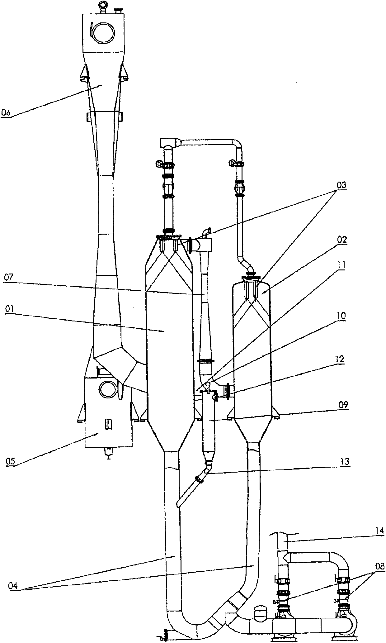
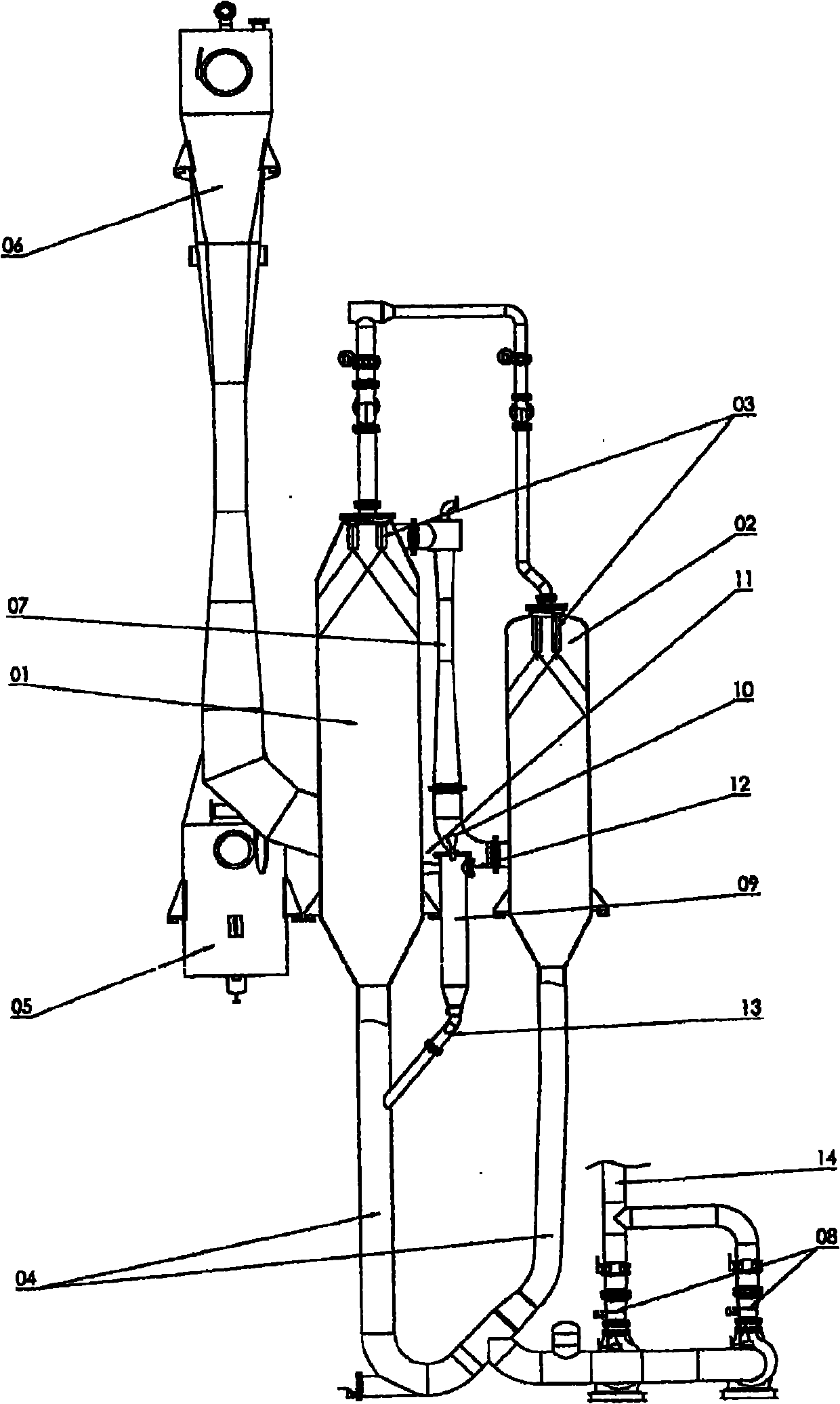
[0022] figure 1 The shown vacuum pump station includes: condensers 1, 2 with cooling water nozzles 3; steam ejectors 5, 6, 7; external liquid level measuring bottle 9, measuring probe 10 and extension Condenser cooling water pump 8 to pressure equalizing pipe 11 of condenser 1 ; and inclined discharge pipe 13 extending into condensate downflow pipe 4 of condenser 1 . The condenser cooling water pump 8 delivers the cooling water through a return line 14 for further treatment of the cooling water, such as a carbon monoxide scrubber (CO washer), a settling tank, etc. not shown here.

[0023] According to the invention, the condensers (1, 2) are measured in a measuring bottle (9) configured to communicate with the vessel and arranged outside the condenser by means of a measuring method suitable for vacuum operation, such as a radar or laser probe (10). level of the cooling water and use the measured value as the controlled variable and signal for the speed-controlled cooling wate...


PUM


Abstract

The invention relates to method and a device for controlling condenser cooling water of a steam-jet vacuum pump in non-barometric installation; wherein an outer measuring pot constructed as communicating container provides the target value for a speed-controlled pump by means of measuring sensors.

Description

technical field [0001] The present invention relates to methods and apparatus for controlling condenser cooling water of steam jet vacuum pumps in non-atmospheric installations. Background technique [0002] Until now, the condenser cooling water level in the condenser of steam jet vacuum pumps in non-atmospheric installations was not controlled. Usually, pumps are used which are operated in a fixed installation and whose delivery volume to the destination of the system is very imprecise. Therefore, the cooling water level is always within the range limited by the level switch and alarm installed in the condenser. [0003] Before the steam jet vacuum pump can be started, the so-called condenser cooling water circuit must be started and run stably. [0004] The start-up of the condenser cooling water in the condenser is carried out under atmospheric pressure. Once the steam jet extractor is connected, which may be combined with a water ring pump, a vacuum is then created a...

Claims


Application Information

Patent Timeline
IPC IPC(8): F04B39/06F04B49/06
CPCF04B23/14F04B49/20F04F5/52
Inventor 哈拉尔德·霍尔兹格鲁伯马丁·勒伯克里斯琴·布克梅尔
Owner INTECO SPECIAL MELTING TECH
Why Eureka
Try Eureka