

Wireless passive measuring method and circuit
A wireless passive, measuring circuit technology, used in in-vivo radio detectors, diagnostic recording/measurement, and the use of electro/magnetic devices to transmit sensing components, etc. Debugging, simple structure, small size effect
- Summary
- Abstract
- Description
- Claims
- Application Information
AI Technical Summary
Problems solved by technology
Method used
Image

Examples
Embodiment 1
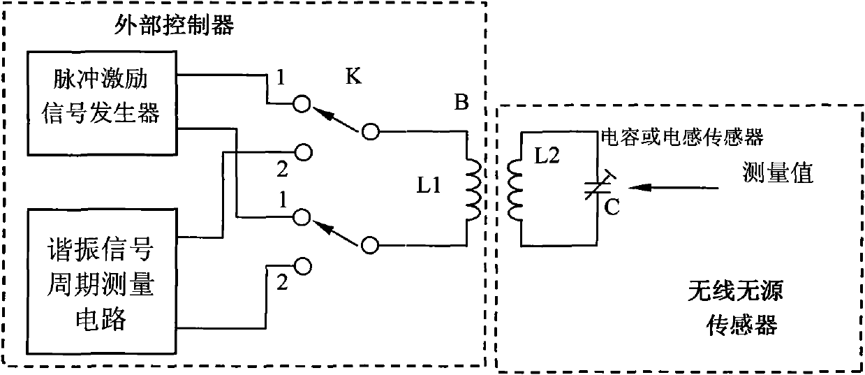
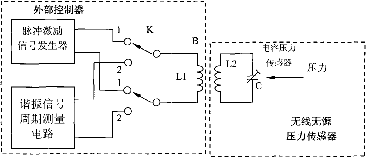
[0010] Embodiment one: if figure 2 As shown, in the wireless passive pressure measurement circuit of the present invention, the capacitive pressure sensor C and the coil L2 form a parallel resonant circuit, and the coil L2 and the detection coil L1 form a loosely coupled transformer B. When measuring, first connect the detection coil L1 of the loosely coupled transformer B to the pulse excitation signal generator through the switch K, and the external circuit generates a pulse signal from the pulse excitation signal generator, and the loosely coupled transformer B excites the capacitive pressure sensor C and the coil L2 A parallel resonant circuit is formed, and then the detection coil L1 of the loosely coupled transformer B is switched to the resonant signal period measurement circuit through the switch K to measure the period of the oscillating signal of the resonant network, and then the pressure value sensed by the capacitive pressure sensor can be obtained by calculation....
Embodiment 2
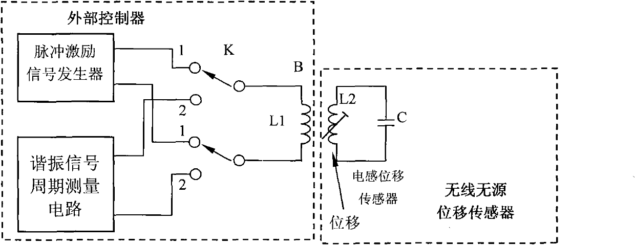
[0023] Embodiment two: if image 3 As shown, in the wireless passive displacement measurement circuit of the present invention, the capacitor C and the inductive displacement sensor L2 form a parallel resonant circuit, and the inductive displacement sensor L2 and the detection coil L1 form a loosely coupled transformer B. When measuring, first connect the detection coil L1 of the loosely coupled transformer B to the pulse excitation signal generator through the switch K, and the external circuit generates a pulse signal from the pulse excitation signal generator, and the excitation capacitor C of the loosely coupled transformer B and the inductive displacement sensor L2 A parallel resonant circuit is formed, and then the coil L1 of the loosely coupled transformer B is switched to the resonant signal period measurement circuit through the switch K to measure the period of the oscillating signal of the resonant network, and then the displacement value sensed by the inductive disp...
PUM
 Abstract
Description
Claims
Application Information