
Depolarization delay device

A delay device and depolarization technology, applied in the field of optical communication, can solve the problem of long depolarization delay structure, and achieve the effect of miniaturization and size reduction

Active Publication Date: 2011-04-06
SHANGHAI BRANCH FUZHOU GAOYI COMM CO LTD
View PDF6 Cites 9 Cited by
  • Summary
  • Abstract
  • Description
  • Claims
  • Application Information

AI Technical Summary

Problems solved by technology

Therefore, there is a defect that the length of the depolarization delay structure is long

Method used


Image

  • Depolarization delay device
  • Depolarization delay device
  • Depolarization delay device

Examples


Embodiment Construction

[0036] The present invention will be further described in conjunction with the accompanying drawings and specific embodiments.

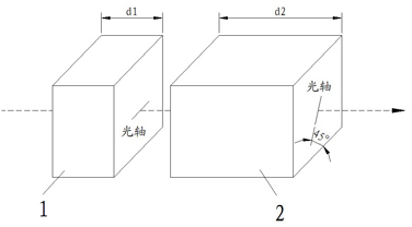
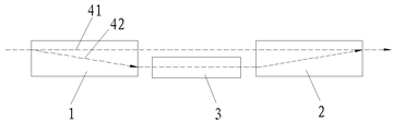
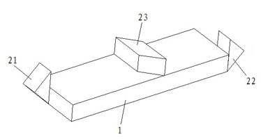
[0037] Such as Figure 4A , Figure 4B , Figure 4C A first embodiment of the device according to the invention is shown, consisting of a birefringent crystal slab 1 , rectangular reflecting prisms 21 , 22 and a rhomboid prism 23 . The right-angle mirrors 21 and 22 are respectively bonded to the light-transmitting surfaces on both sides of the birefringent crystal slab 1 with an adhesive, and the orthorhombic prism 23 is bonded and fixed to the upper surface of the birefringent crystal slab 1 . When the incident light 30 is incident on the birefringent crystal slab 1, due to the birefringence effect of the crystal, the light beam will be separated into o light 301 (the light polarization direction is perpendicular to the plane of the optical axis 11 of the birefringent crystal slab) and e light 302 (The direction of light polarization is parallel ...


PUM


Abstract

The invention relates to a phase delay device capable of realizing Raman pump light depolarization. A depolarization delay device uses a light separation and beam gathering element for firstly separating input light beams entering from a specific incidence point into a first sub light beam and a second sub light beam vertical to the first sub light beam in the polarization direction, the first sub light beam is output from a specific emergent point along an original light path, the second sub light beam is reflected to the second position point deviating from the original light path at the other end of the light separation and beam gathering element from the first position point of the light separation and beam gathering element deviating from the original light path and is then reflectedto enter the light separation and beam gathering element so that the second sub light beam can be output from the special emergence point after being gathered with the first sub light beam into one beam. Compared with the prior art, the depolarization delay device greatly reduces the dimension of the depolarization delay structure so that the miniaturization of a light module is realized favorably.

Description

technical field [0001] The invention relates to the field of optical communication, in particular to a phase delay device capable of realizing polarization and depolarization of Raman pump light. Background technique [0002] Raman fiber amplifier (RFA) has the advantages of wide gain bandwidth (1292-1660nm), flexible gain spectrum, good temperature stability, low spontaneous emission noise, and ordinary optical fiber as gain medium. It can be used in 40G / 100G It is widely used in transmission network. However, since the pump light is polarized light, that is, the degree of polarization (DOP) is large, this will cause the polarization-dependent gain (PDG) of the Raman fiber amplifier to be too large, thereby affecting the gain balance of the amplifier, so it is usually necessary to pump it Puguang depolarization treatment. [0003] The existing common polarization depolarization technologies mainly include spatial depolarization, time domain depolarization and frequenc...

Claims


Application Information

Patent Timeline
IPC IPC(8): G02B27/28G02B17/02
Inventor 蔡宏铭陈斯杰林斌吴砺王冬寒
Owner SHANGHAI BRANCH FUZHOU GAOYI COMM CO LTD
Features
  • Generate Ideas
  • Intellectual Property
  • Life Sciences
  • Materials
  • Tech Scout
  • Unparalleled Data Quality
  • Higher Quality Content
  • 60% Fewer Hallucinations
Learn More