
Instantaneous milling force modeling method in free curve shape part peripheral milling process

A technology of instantaneous milling force and circumferential milling, applied in special data processing applications, instruments, electrical digital data processing, etc., can solve the problem of reducing the computational workload of the instantaneous milling force modeling method and the large computational workload of the instantaneous milling force modeling method. And other issues

Active Publication Date: 2011-04-06
NORTHWESTERN POLYTECHNICAL UNIV
View PDF3 Cites 27 Cited by
  • Summary
  • Abstract
  • Description
  • Claims
  • Application Information

AI Technical Summary

Problems solved by technology

[0012] In order to overcome the shortcomings of the existing modeling method of instantaneous milling force during the peripheral milling process of free-curve parts, the present invention provides a method for modeling instantaneous milling force during the peripheral milling of free-curve parts. The method firstly adopts The sampling time interval calculates the corresponding tool position points at each moment, and calculates the geometric parameters corresponding to each tool position point at the same time, and then establishes the numerical calculation model of the cut-in / cut-out angle in the local coordinate system and the instantaneous undeformed chips through mathematical derivation The analytical model of the thickness, and finally establish the relationship between the instantaneous milling force in the local coordinate system and the instantaneous undeformed chip thickness, and project the instantaneous milling force in the local coordinate system to the global coordinate system, which can reduce the peripheral milling process of the free curve shape parts. Computational Workload of Instantaneous Milling Force Modeling Method

Method used


Image

  • Instantaneous milling force modeling method in free curve shape part peripheral milling process
  • Instantaneous milling force modeling method in free curve shape part peripheral milling process
  • Instantaneous milling force modeling method in free curve shape part peripheral milling process

Examples


Embodiment 1

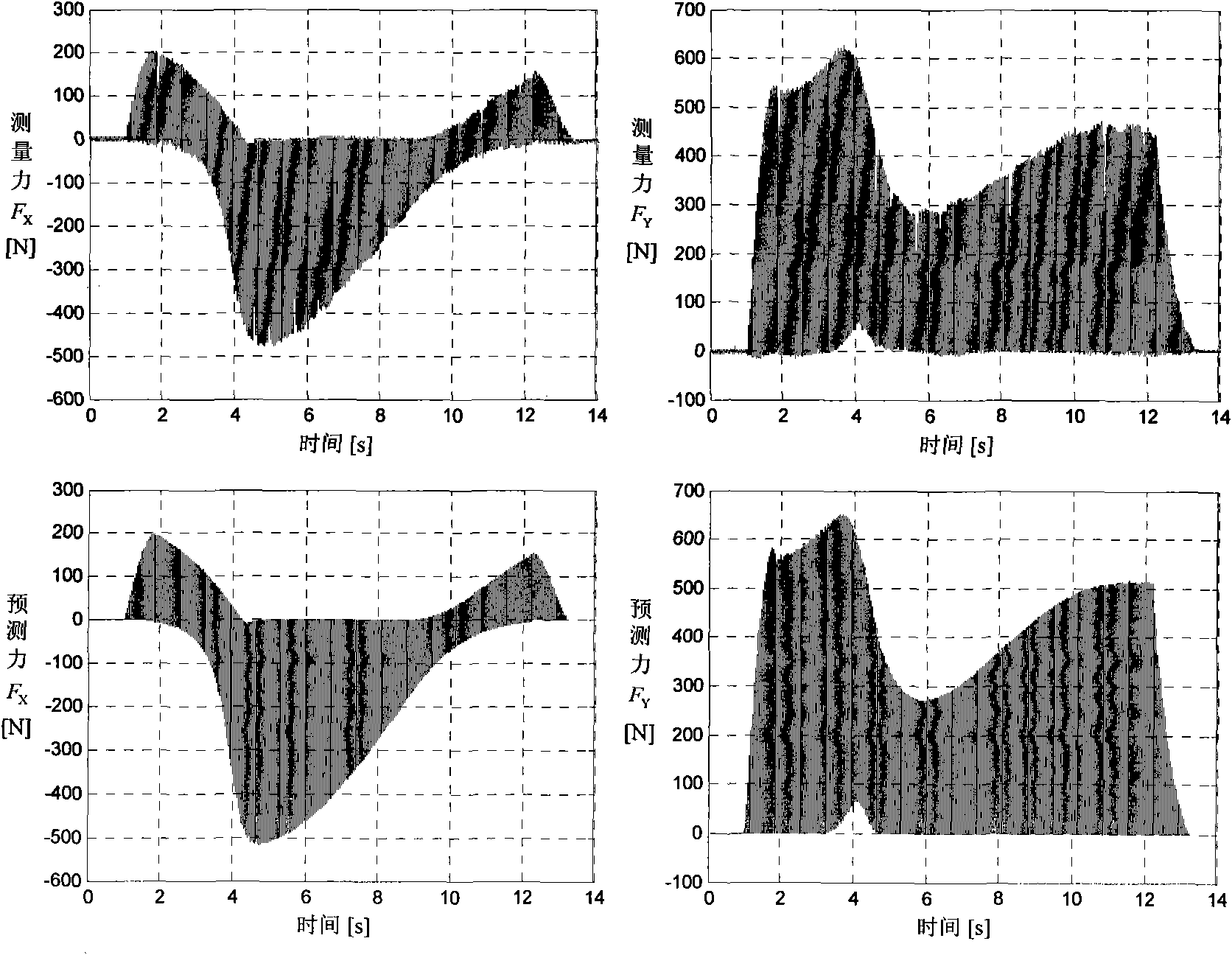
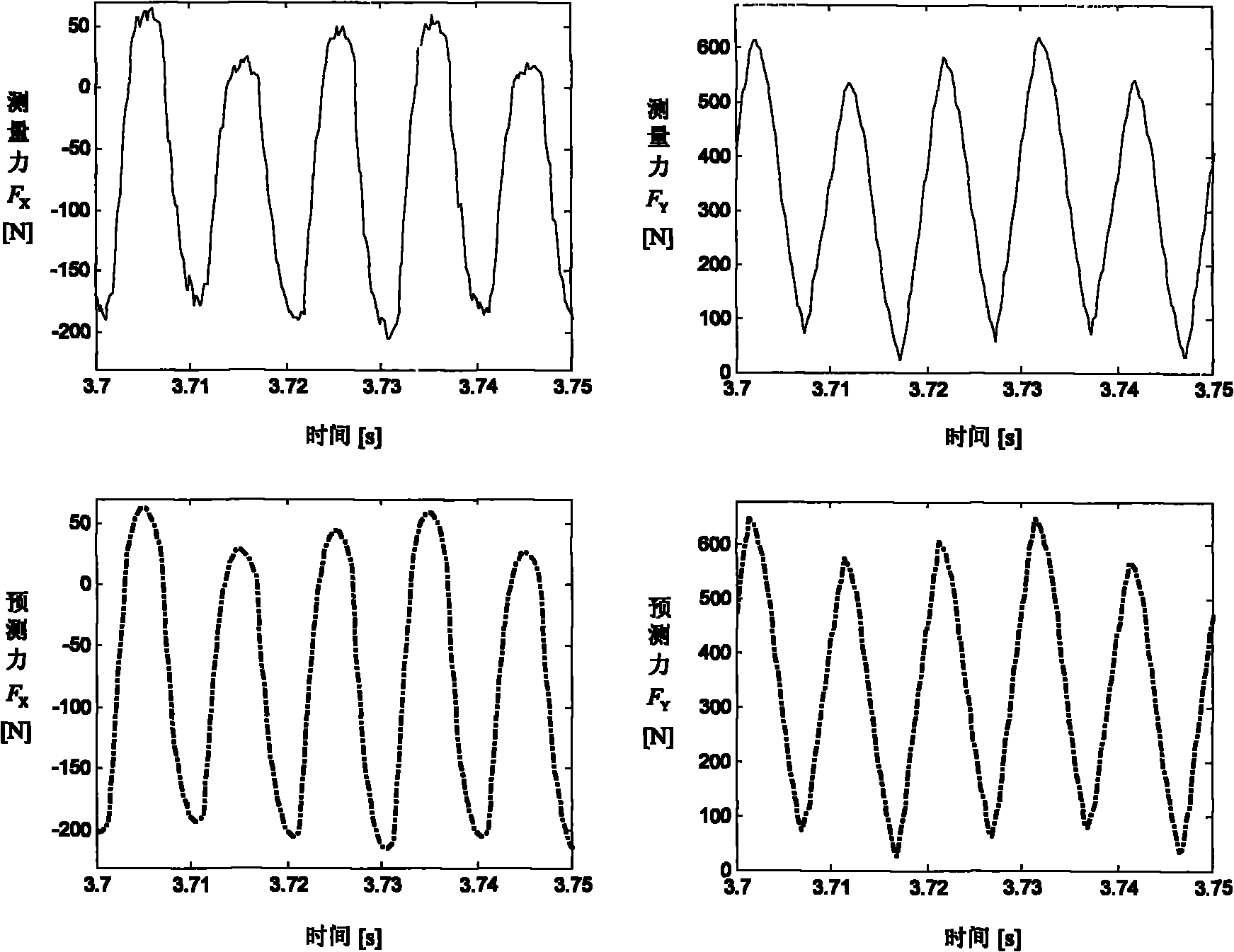
[0081] Embodiment 1: (1) selected radius RAD=6mm, helix angle β 0 A three-tooth carbide end mill with = 30 degrees performs down milling on aluminum alloy Al7050 on a three-coordinate end milling machine, the tool eccentricity parameters ρ = 0.0026 and λ = 31.8°, the spindle speed n = 2000RPM, and the feed rate V f =300mm / min, axial depth of cut R z = 10mm, radial depth of cut R r =3mm, sampling time interval T s =0.0002s, input the vector equation p(u)=[X(u), Y(u), Z(u)] ​​of the workpiece to obtain the surface T , where

[0082] X(u)=20+105u(1-u) 2 +15u 2 (1-u)+40u 3

[0083] Y(u)=5+90u 2 (1-u)+30u 3 u ∈ [0, 1]

[0084] 0≤Z(u)≤10

[0085] The vector equation p of the blank boundary W (v)=[X W (v), Y W (v), Z W (v)] T , where

[0086] X W ( v ) = 20 + 105 v ( 1 - v ...

Embodiment 2

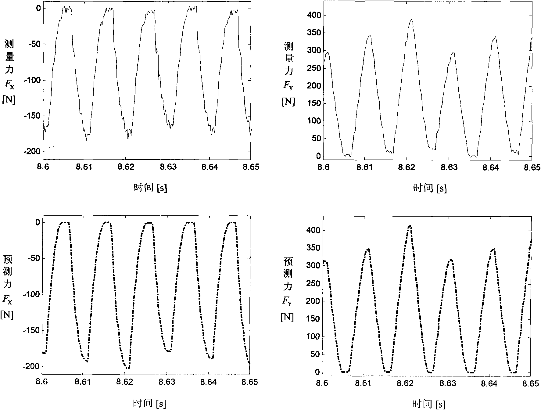
[0193] Embodiment 2: (1) selected radius RAD=6mm, helix angle β 0 A three-tooth carbide end mill with = 30 degrees performs down milling on aluminum alloy Al7050 on a three-coordinate end milling machine. The tool eccentricity parameters ρ = 0.0026 and λ = 31.8°, the spindle speed n = 2000RPM, and the feed rate V f =450mm / min, axial depth of cut R z = 10mm, radial depth of cut R r =3mm, sampling time interval T s =0.0002s, input the vector equation p(u)=[X(u), Y(u), Z(u)] ​​of the workpiece to obtain the surface T , where

[0194] X(u)=20+105u(1-u) 2 +15u 2 (1-u)+40u 3

[0195] Y(u)=5+90u 2 (1-u)+30u 3 u ∈ [0, 1]

[0196] 0≤Z(u)≤10

[0197] The vector equation p of the blank boundary W (v)=[X W (v), Y W (v), Z W (v)] T , where

[0198] X W ( v ) = 20 + 105 v ( 1 - v ...


PUM


Abstract

The invention discloses an instantaneous milling force modeling method in the free curve shape part peripheral milling process, used for solving the technical problem of big calculation working capacity of the traditional instantaneous milling force modeling method in the free curve shape part peripheral milling process. The invention has the technical scheme that the equivalent feed direction, the equivalent normal vector and the equivalent curvature which correspond to an equivalent tool position on a theoretical tool path replace the feed direction, the normal vector and the curvature which correspond to the tool position on the actual tool path so as to avoid the phenomenon of the forecasted milling force mutation caused by using a non-second order continuous actual tool path forecasted milling force; while the eccentricity is considered, an analytic model of instantaneous undeformed cutting thickness is deduced, and the instantaneous undeformed cutting thickness does not need to be worked out by using a numerical calculation method. By utilizing the method, the time for calculating the instantaneous milling forces of 10 periods in a personal computer (Inter Core (TM) 2Duo Processor, 2.4GHz, 2GB) by using an MATLAB is 1.9s, while the time for calculating by adopting the method of a document 2 is 233.3s, and the calculation efficiency is improved by 122.79 times.

Description

technical field [0001] The invention relates to a modeling method of instantaneous milling force in the process of circumferential milling, in particular to a modeling method of instantaneous milling force in the process of circumferential milling of parts with free curve shapes. Background technique [0002] Circumferential milling is a mechanical processing method that cuts off excess material layers on the surface of the material by an end mill to obtain the ideal workpiece shape, size and surface finish. It is the most commonly used in machining various molds, auto parts and aerospace parts in mechanical manufacturing. one of the ways. In the process of circumferential milling, many problems such as tool wear, tool breakage, machining chatter and machining deformation often occur, which seriously affect the machining accuracy and machining efficiency of parts. In order to overcome the above problems, it is necessary to establish a milling force prediction model in perip...

Claims


Application Information

Patent Timeline
IPC IPC(8): G06F17/50
Inventor 张卫红杨昀党建卫王怡婷万敏
Owner NORTHWESTERN POLYTECHNICAL UNIV
Features
  • Generate Ideas
  • Intellectual Property
  • Life Sciences
  • Materials
  • Tech Scout
  • Unparalleled Data Quality
  • Higher Quality Content
  • 60% Fewer Hallucinations
Learn More