Broadcast signal conversion device

A technology of broadcast signal and conversion device, applied in image communication, television, two-way working system, etc., can solve problems such as trouble, and achieve the effect of reducing power consumption and improving convenience

Inactive Publication Date: 2011-04-06
SANYO ELECTRIC CO LTD
View PDF5 Cites 0 Cited by
  • Summary
  • Abstract
  • Description
  • Claims
  • Application Information

AI Technical Summary

Problems solved by technology

Even if this function is provided, the salesperson must individually set the power consumption of each broadcast receiving device, which is quite troublesome.

Method used


Image

  • Broadcast signal conversion device
  • Broadcast signal conversion device
  • Broadcast signal conversion device

Examples


Embodiment approach 1

[0055]

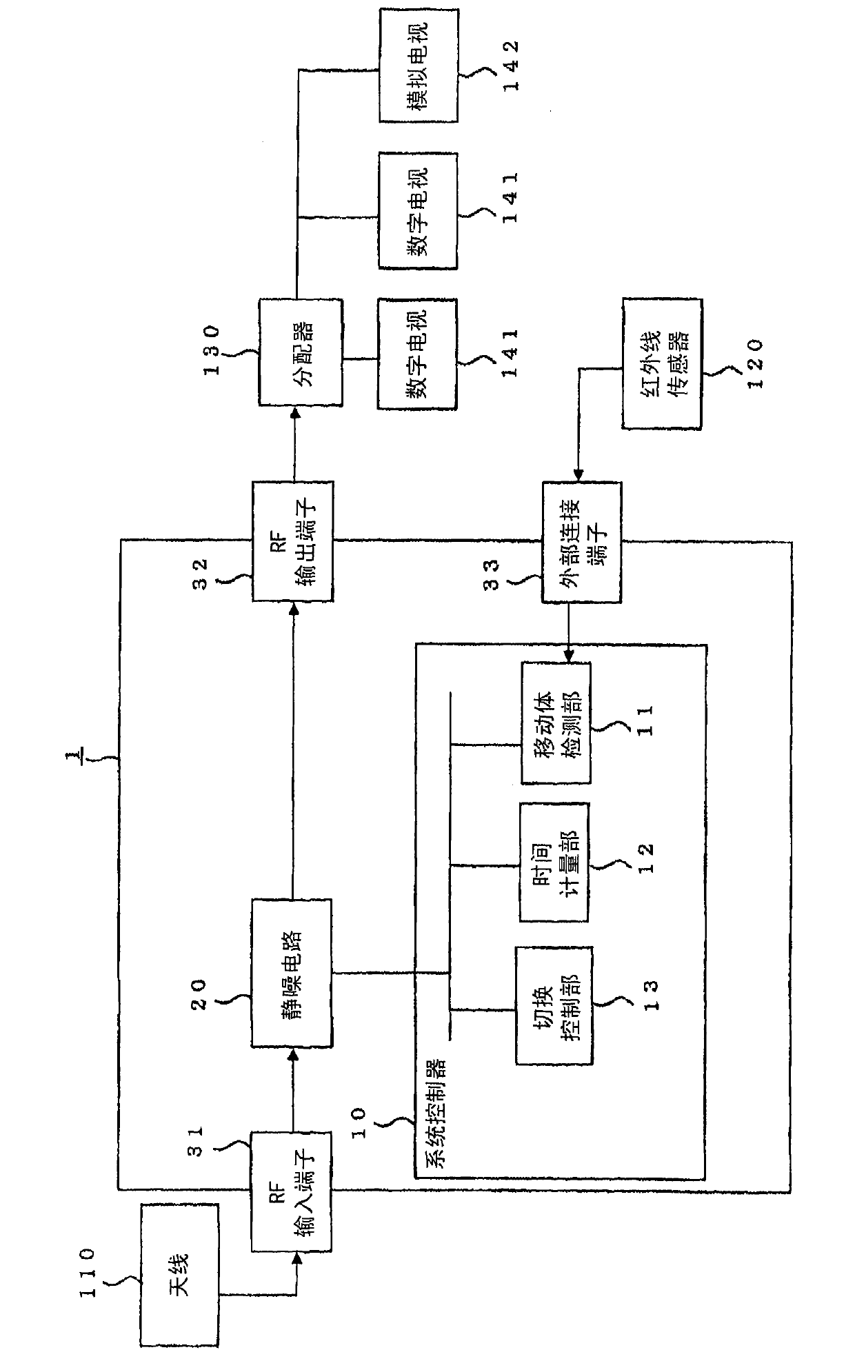
[0056] figure 1 It is a block diagram showing the internal configuration of the broadcast signal conversion device 1 according to the first embodiment of the present invention. The broadcast signal conversion device 1 is configured to include at least a system controller 10, a mute circuit (=switching unit) 20 (=switching unit), an RF input terminal 31 (=signal input unit), and an RF output terminal 32 (=signal output unit). , and the external connection terminal 33 (=connection portion).

[0057] The system controller 10 performs overall control of RF signal input / output processing, RF signal conversion processing, and the like by controlling the driving of each component of the broadcast signal conversion device 1 . The system controller 10 is constituted by, for example, a plurality of microprocessors.

[0058] Furthermore, the system controller 10 includes a moving object detection unit 11 , a time measurement unit 12 , and a switching control unit 13 as funct...

Embodiment approach 2

[0080]

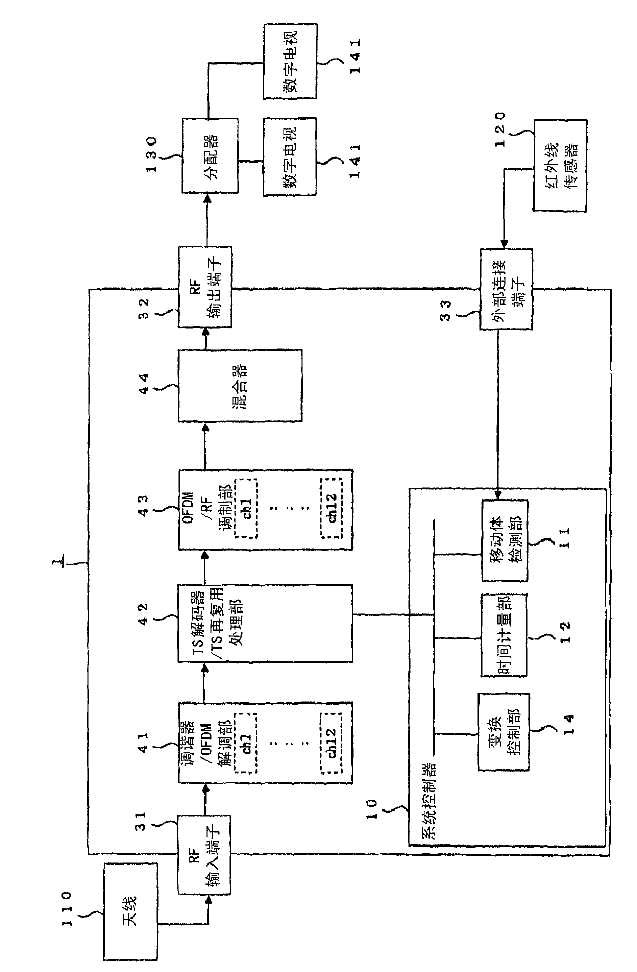
[0081] image 3It is a block diagram showing the internal configuration of the broadcast signal conversion device 1 according to the second embodiment of the present invention. The broadcast signal conversion device 1 of the present embodiment performs conversion processing of an RF signal for digital broadcasting. Therefore, instead of the squelch circuit 20 of Embodiment 1, it is configured to include a tuner / OFDM (orthogonal frequency division multiplex) demodulation unit 41 (=demodulation unit), and a TS (transport stream) decoding / TS remultiplexing processing unit. 42 (=transformation section), OFDM / RF modulation section 43 (=modulation section), and mixer 44 .

[0082] The tuner / OFDM demodulation unit 41 performs high-frequency processing and demodulation of the RF signal input from the antenna 10 . The broadcast signals of a plurality of channels obtained by demodulation are supplied to the TS decoder / TS remultiplexing processing unit 42 . in e.g. image ...


PUM


Abstract

The invention provides a broadcast signal conversion device, capable of reducing the consumed electric power of a self-luminescence type monitoring device and a loudspeaker even though without a broadcast receiving device with the consumed electric power reduction function. The broadcast signal conversion device comprises a switching part for switching on / off the signal of the transmission path for transmitting the signal from a signal input part to a signal output part. A connection part is connected with a moving body detection device for detecting the moving body. A moving body detection part receives the moving body detection signal from the moving body detection device. A switch control part controls the switching part when not receiving the moving body detection signal to cut off the signal in the transmission path. A time measurement part measures the passing time after the receiving state of the moving body detection signal is changed. When the passing time measured by the time measurement part exceeds the preset time, the switch control part controls the switching part to switch the on / off of the signal in the transmission path.

Description

technical field [0001] The present invention relates to a broadcast signal conversion device which inputs and converts a broadcast signal, and more particularly relates to a broadcast signal conversion device which can change the converted broadcast signal output status according to the status of viewers who watch and listen to the broadcast. Background technique [0002] Currently, television sets, radio sets, and the like are widely used as broadcast receiving apparatuses that receive broadcast waves and output video, audio, and the like. Broadcasting includes CS (Communication Satellite: Communication Satellite) digital broadcasting, BS (Broadcast Satellite: Broadcasting Satellite) digital / analog broadcasting, terrestrial digital / analog broadcasting, and the like using satellites. [0003] Regarding terrestrial TV broadcasting, it has been decided that in 2011, terrestrial analog broadcasting will be discontinued and digital broadcasting will be switched. Digital broadca...

Claims


Application Information

Patent Timeline
Patent Type & Authority Applications(China)
IPC IPC(8): H04N5/44H04N7/26H04N7/173H04N21/436H04N21/442
Inventor 胁坂雅子
Owner SANYO ELECTRIC CO LTD
Why Eureka
Try Eureka