Vehicle drive device

A technology of driving device and fluid transmission device, which is applied in the direction of power device, transmission device, fluid transmission device, etc., to achieve the effects of restraining enlargement, reducing heat release, improving controllability and transmitting torque capacity

Inactive Publication Date: 2011-04-06
AISIN AW CO LTD
View PDF7 Cites 10 Cited by
  • Summary
  • Abstract
  • Description
  • Claims
  • Application Information

AI Technical Summary

Problems solved by technology

However, simply replacing the two clutches from a single-plate type to a multi-plate type will cause a new problem of increasing the size of the fluid drive device.

Method used


Image

  • Vehicle drive device
  • Vehicle drive device
  • Vehicle drive device

Examples


Embodiment Construction

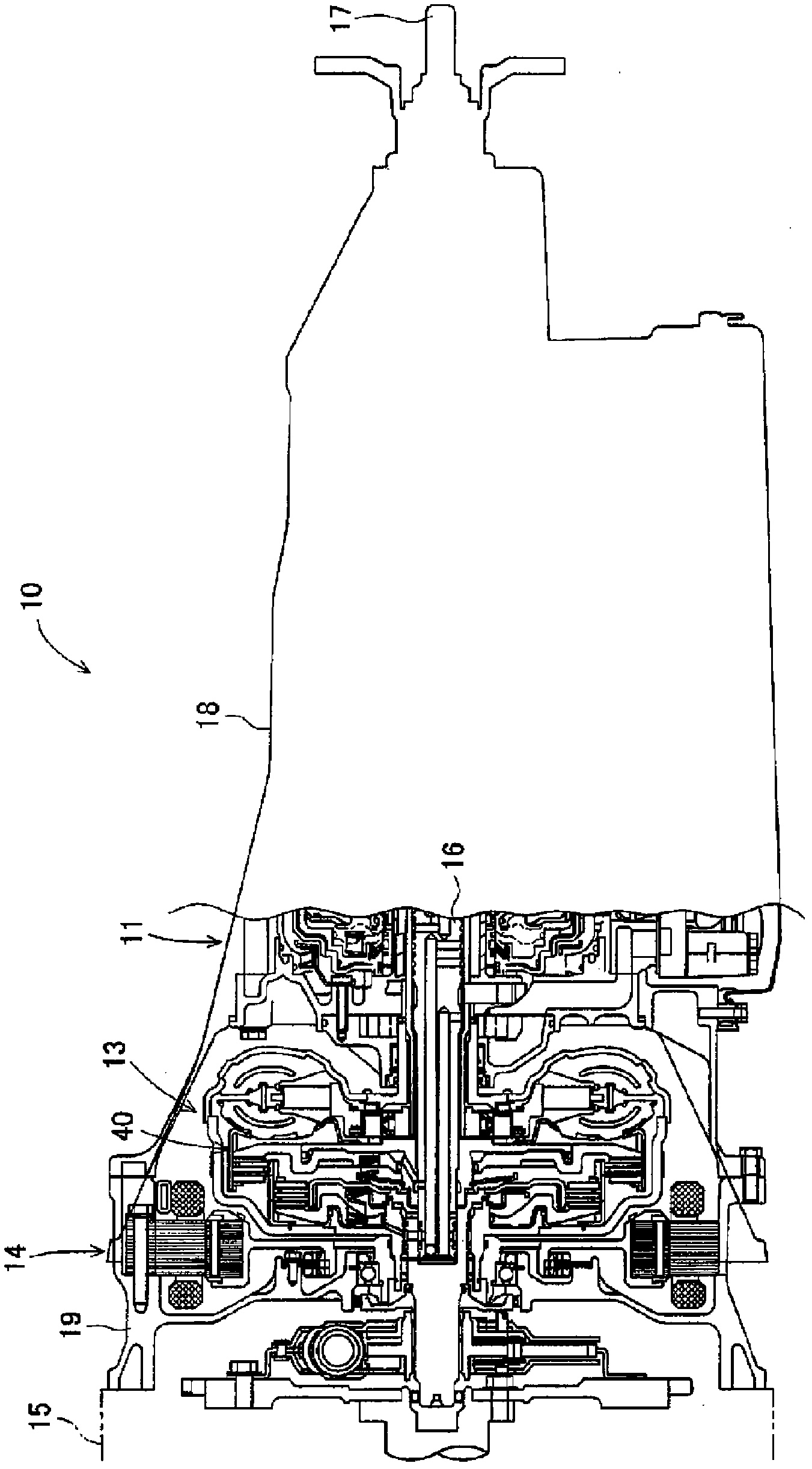
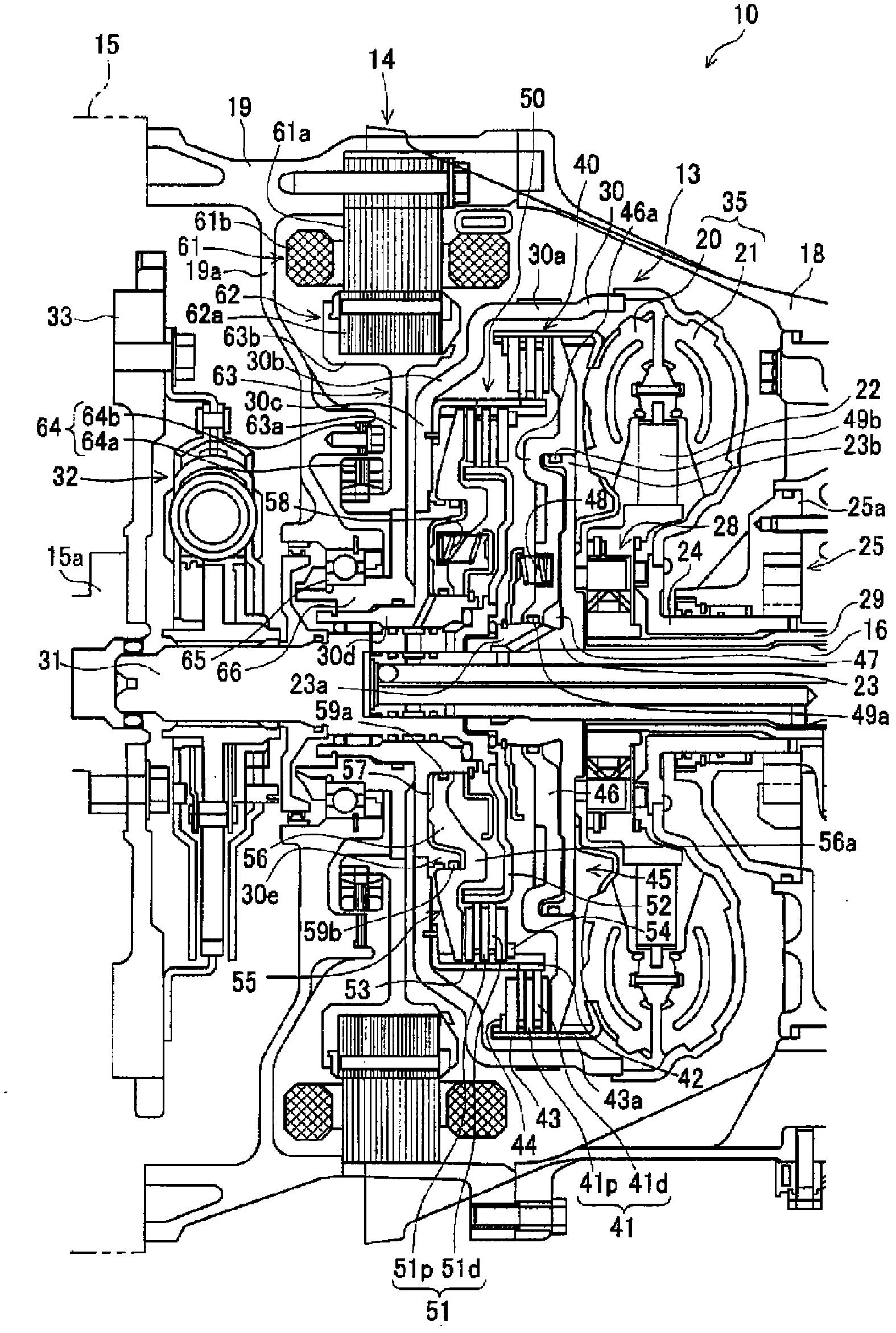
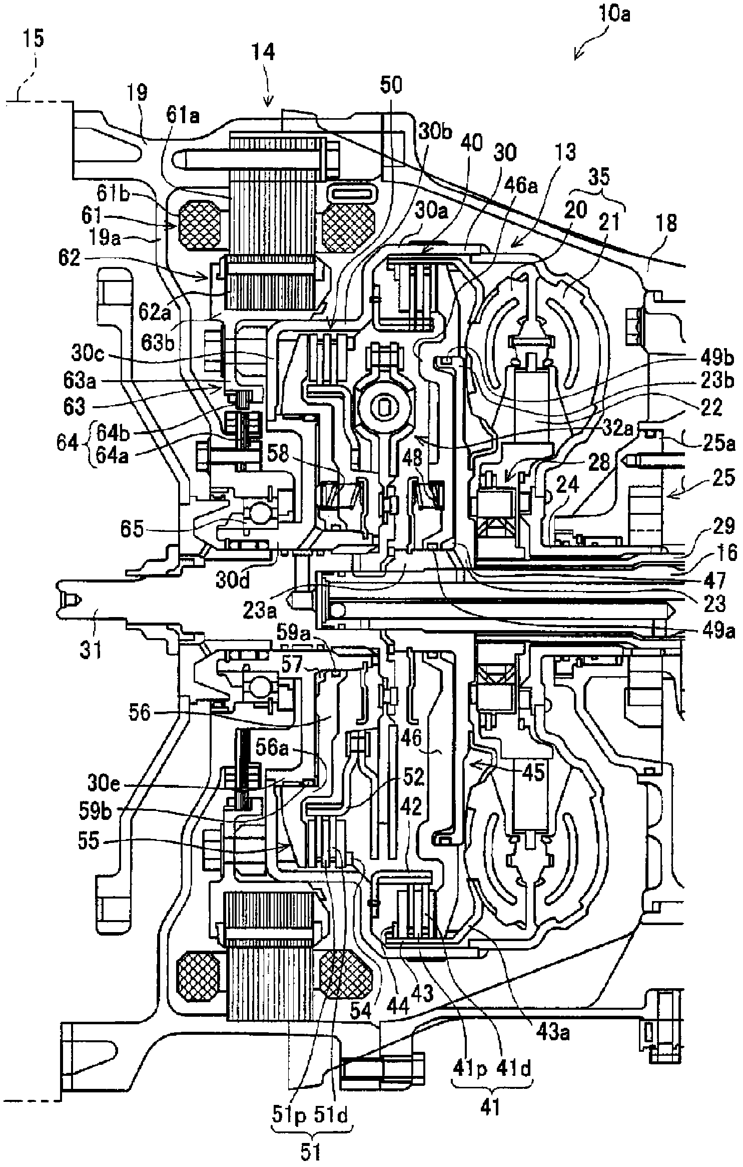
[0031] Hereinafter, preferred embodiments in which the vehicle drive device of the present invention is realized will be described in detail with reference to the drawings. In this embodiment, a single-motor parallel-type hybrid vehicle drive device will be described. So, in reference tofigure 1 and figure 2 At the same time, the driving device of the embodiment will be described. figure 1 It is a partial cross-sectional view showing a schematic configuration of the drive device according to the embodiment. figure 2 It is an enlarged sectional view of the vicinity of the torque converter in the drive device of the embodiment.

[0032] Such as figure 1 As shown, the driving device 10 includes: a multi-stage transmission mechanism 11 accommodated in a transmission body 18, a torque converter 13 having a lock-up clutch, a motor-generator composed of a brushless DC motor and the like and accommodated in a motor housing 19. machine14. In addition, the drive unit 10 is figur...


PUM


Abstract

A drive device for a vehicle, having an engine power disengaging clutch mounted in a lockup clutch-equipped fluid power transmitting device, wherein controllability and torque transmission capacities of both the clutches are increased, the amount of heat generation of friction materials when the clutches are engaged is reduced, the drive device allows a fluid drive device to be configured withoutan increase in the size thereof, and the drive device is configured without an increase in the size thereof. The lockup clutch and the engine power disengaging clutch are respectively formed as multi-plate clutches having actuators. Friction plates of the lockup clutch are provided on the outer diameter side of a torus. The engine power disengaging clutch is formed to have a smaller diameter thanthe lockup clutch. The engine power disengaging clutch is provided in a torque converter. On the outer diameter side of the engine power disengaging clutch, a motor generator is mounted overlapping axially the friction plates of the engine power disengaging clutch.

Description

technical field [0001] The present invention relates to a driving device for a hybrid vehicle having an engine and a motor as a driving source, and more specifically, to a driving device for a vehicle including an engine power interruption clutch in a fluid transmission device with a lockup clutch. Background technique [0002] As a drive device mounted on a hybrid vehicle, a drive device that transmits rotation generated by a drive source to a transmission mechanism via a fluid transmission device with a lockup clutch is widely used. In addition, such a drive device is provided with an engine power interruption clutch that transmits or interrupts the driving force of the engine with respect to the fluid transmission device. Here, the lock-up clutch is a component used to transmit the driving force generated by the power source to the transmission mechanism without passing through the fluid. Once the vehicle speed reaches a preset speed, it will be activated (locked up) to i...

Claims


Application Information

Patent Timeline
Patent Type & Authority Applications(China)
IPC IPC(8): B60K6/387B60K6/40B60K6/48B60K6/547F16H45/00F16H45/02
CPCY02T10/6226B60K6/485F16H2045/002F16H2045/0284B60K6/387B60K6/48B60W10/02B60K6/547F16H45/02F16H2045/021Y02T10/6221B60K6/405B60W20/00Y02T10/62B60W20/15B60W10/08B60W10/10
Inventor 铃木智英糟谷悟岩濑干雄
Owner AISIN AW CO LTD
Why Eureka
Try Eureka