Synthesis method of multifrequency synchronous signal source

A technology of synchronous signal and synthesis method, which is applied in medical science, sensors, diagnostic recording/measurement, etc., and can solve the problems that synchronous excitation signal cannot meet the requirements of data processing, low cost, and hardware is difficult to implement.

Inactive Publication Date: 2011-04-13
XIAN UNIV OF TECH
View PDF3 Cites 12 Cited by
  • Summary
  • Abstract
  • Description
  • Claims
  • Application Information

AI Technical Summary

Problems solved by technology

As far as the current technology is concerned, it is relatively easy to synchronize two signals on the same DDS chip, but it is difficult to achieve synchronization between more signals generated by different DDS chips. or low-cost implementation
The theoretical basis of BIS technology is the Cole-Cole impedance model, and the four parameters of the Cole-Cole imped

Method used


Image

  • Synthesis method of multifrequency synchronous signal source
  • Synthesis method of multifrequency synchronous signal source
  • Synthesis method of multifrequency synchronous signal source

Examples


Embodiment 1

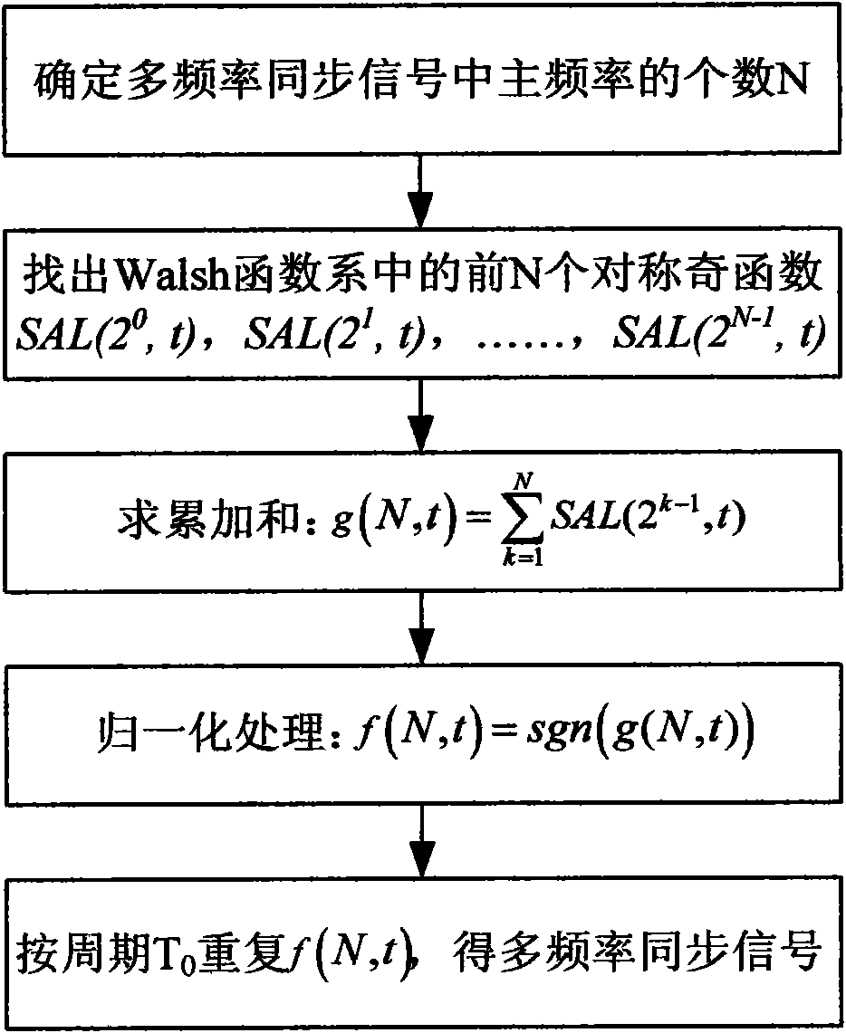
[0042] Embodiment 1: According to figure 1 In the synthesis steps shown, the five-frequency synchronization signal f(5, t) is synthesized.

[0043] Step 1, select N=5, it can be known that f(5, t) in a cycle T 0 The inner signal is subdivided into 32 equal parts.

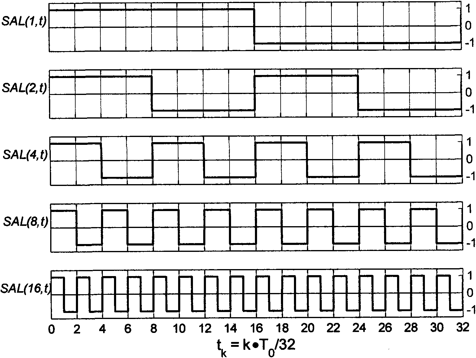
[0044] Step 2, find out the first five symmetric odd functions SAL(2 0 , t), SAL(2 1 , t), SAL(2 2 , t), SAL(2 3 , t), SAL(2 4 , t), represent them as binary vectors of length 32, such as figure 2 shown.

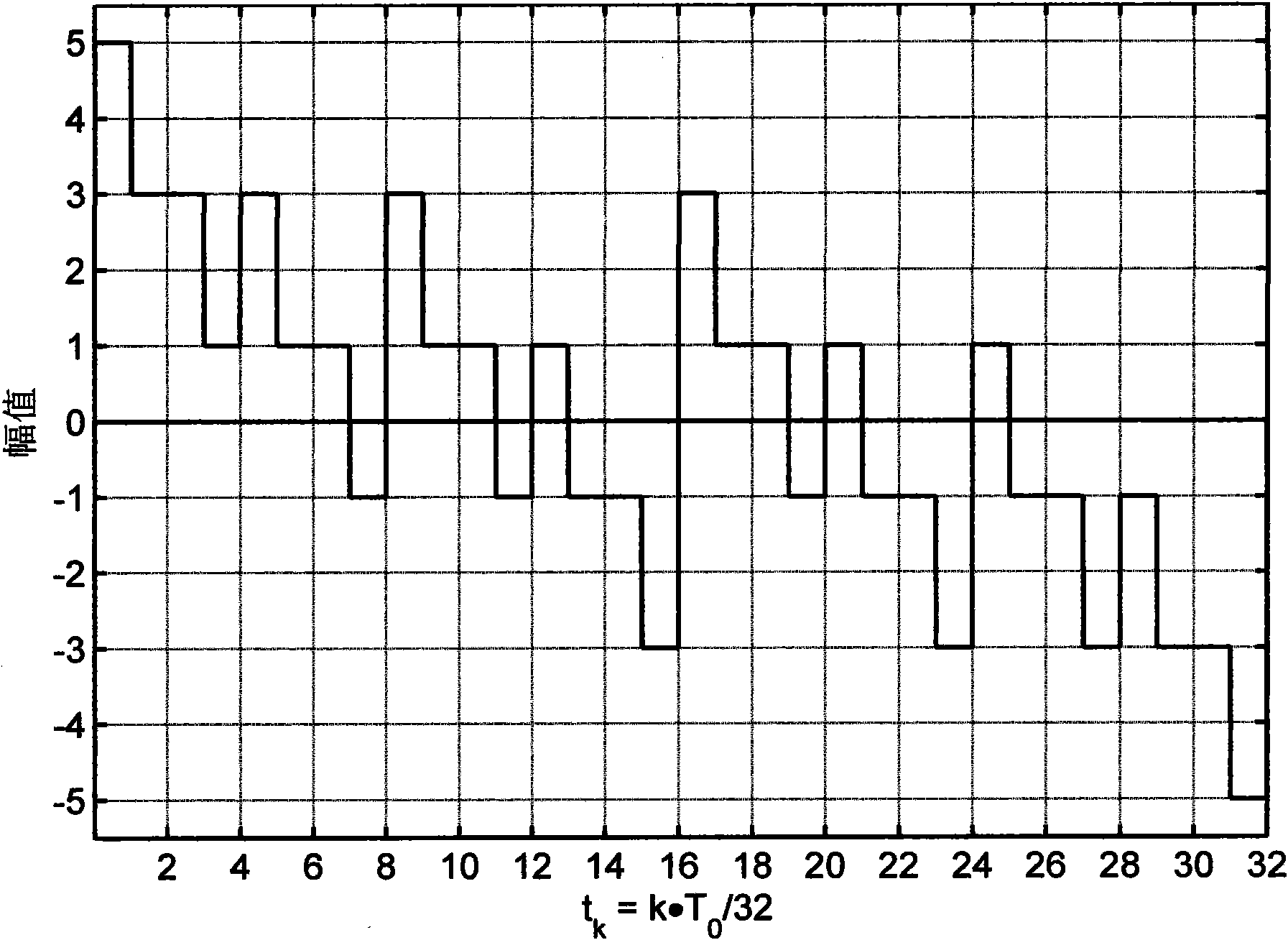
[0045] Step 3, accumulate and sum the five vectors to obtain the accumulated sum vector g(5, t), such as image 3 As shown, the cumulative sum vector is a multivalued piecewise linear function.

[0046] Step 4, use the sign function sgn() to normalize the accumulated sum vector g(5, t), so that a five-frequency synchronization signal with only two values ​​of +1 and -1 can be obtained in a cycle T 0 The vector f(5, t) inside, it is expressed as a vector form containing 32 elements in a period: f(5, t)=[...

Embodiment 2

[0070] Embodiment 2: According to figure 1 In the synthesis steps shown, the seven-frequency synchronization signal f(7, t) is synthesized.

[0071] Step 1, select N=7, it can be seen that f(7, t) in a cycle T 0 The inner signal is subdivided into 128 equal parts.

[0072] Step 2, find out the first seven symmetric odd functions SAL(2 0 , t), SAL(2 1 , t), SAL(2 2 , t), SAL(2 3 , t), SAL(2 4 , t), SAL(2 5 , t), SAL(2 6 , t), expressing them as binary vectors of length 128, such as Figure 7 shown.

[0073] Step 3, accumulate and sum the seven vectors to obtain the accumulated sum vector g(7, t), such as Figure 8 shown. Depend on Figure 8 It can be seen that the cumulative sum vector is a multivalued piecewise linear function.

[0074] Step 4, use the sign function sgn() to normalize the accumulated sum vector g(7, t), so as to obtain a seven-frequency synchronous signal with only two values ​​of +1 and -1 in a cycle T 0 The vector f(7, t) inside, it is expresse...


PUM


Abstract

The invention discloses a synthesis method of a multifrequency synchronous signal source, comprising the following steps of, determining an amount N of main frequencies in a multifrequency synchronous signal to be synthesized, thereby determining that the signal is subdivided into 2N equal parts within a period T0, wherein N should be an odd number; finding out vectors of first N symmetric odd functions SAL (20, t), SAL (21, t), ......, SAL (2N-1, t) in a Walsh function system within a period, wherein each vector contains 2N elements; summing N vectors to obtain a sum vector g (N, t); carrying out normalization treatment on the sum vector g (N, t) with a sign function sgn () pair, thereby obtaining vectors f (N, t) of multifrequency synchronous signals of +1 and -1 within the period T0; and repeating the f (N, t) with a fundamental frequency period T0 to obtain a periodic multifrequency synchronous signal. The multifrequency synchronous signal source synthesized through the method has various very ideal time domain and frequency domain characteristics and realizes multifrequency synchronous measurement of an impedance spectroscopy.

Description

technical field [0001] The invention belongs to the technical field of medical electronic instruments and test measurement, and relates to a method for synthesizing a multi-frequency synchronous signal source. Background technique [0002] As a non-invasive detection method, Bioimpedance Spectroscopy (BIS) technology has broad application prospects in the monitoring of human physiological and pathological parameters. BIS measurement usually applies a small alternating current or voltage signal to the measured object by means of excitation electrodes placed on the body surface, and at the same time detects the voltage or current signal on the tissue surface through the measurement electrodes, and calculates the corresponding electrical impedance and To obtain relevant physiological and pathological information. The technology is cheap, safe, non-toxic and harmless, easy to operate, etc., and has broad application prospects. [0003] All current BIS measurement methods are e...

Claims


Application Information

Patent Timeline
IPC IPC(8): A61B5/053
Inventor 杨宇祥
Owner XIAN UNIV OF TECH
Why Eureka
Try Eureka