Floating-charge type heat-accumulation power generation device

A power generation device and heat storage technology, which is applied to steam engine devices, machines/engines, mechanical equipment, etc., can solve the problems of large gas storage capacity and large gas tank volume, and achieve high thermal efficiency and stable thermal energy

Inactive Publication Date: 2011-04-13
王志江
View PDF5 Cites 0 Cited by
  • Summary
  • Abstract
  • Description
  • Claims
  • Application Information

AI Technical Summary

Problems solved by technology

Due to the large volume and large gas storage capacity of the

Method used


Image

  • Floating-charge type heat-accumulation power generation device
  • Floating-charge type heat-accumulation power generation device

Examples


Embodiment Construction

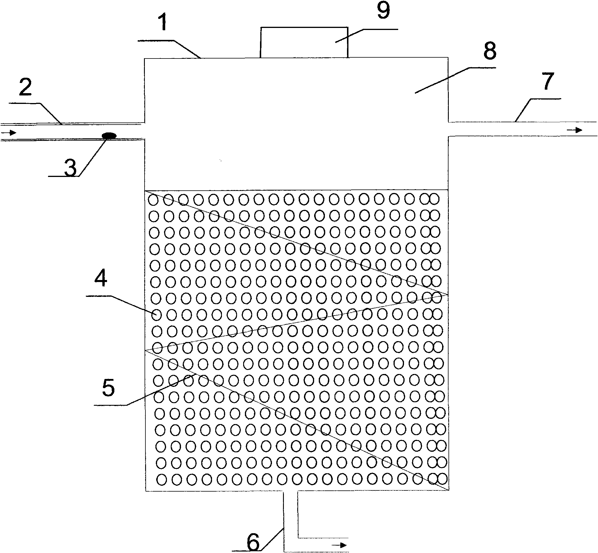
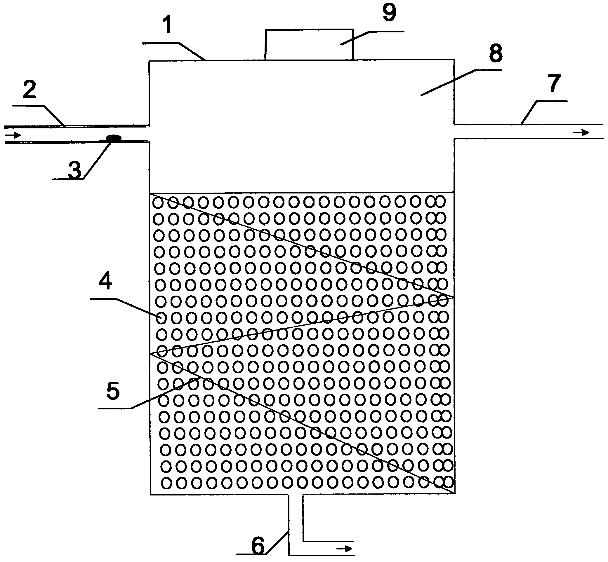
[0022] Fig. 1 shows the overall structure of the present embodiment:

[0023] It consists of a constant temperature heat accumulator and a power generation system 8. The constant temperature heat accumulator is composed of a gas tank 1, a heat storage body 4, an air inlet pipe 2, an air outlet pipe 7 and an exhaust pipe 6. Gas tank 1 has a diameter of 5 meters and a height of 10 meters, and its inner cavity is equipped with multiple heat accumulators 4; the intake pipe 2 that introduces high-temperature exhaust gas is passed into the upper combustion chamber 8 of the gas tank; the gas tank 1 corresponding to the intake pipe 2 On the other side, a gas outlet pipe 7 communicates with the power generation system 8; an exhaust gas pipe 6 protrudes through the bottom of the gas tank. The top of the gas tank 1 is provided with a movable cover 9.

[0024] The folded partition 5 is arranged in the gas tank, and the folded partition 5 is covered with holes, which is beneficial for ad...


PUM


Abstract

The invention discloses a floating-charge type heat-accumulation power generation device. The power generation device consists of a constant temperature heat accumulator and a power generation system, wherein the constant temperature heat accumulator consists of a gas tank, heat accumulators, a gas inlet pipe, a gas outlet pipe and an exhaust gas pipe, a plurality of heat accumulators are arranged in the inner chamber of the gas tank; the gas inlet pipe introducing high-temperature exhaust gas is led into the tank from the upper part of the gas tank; the other side of the gas tank corresponding to the gas inlet pipe is provided with the gas outlet pipe and is communicated with the power generation system; and the exhaust gas pipe passes through the bottom part of the gas tank and is extended out. The heat accumulators have honeycomb shapes and are prepared from the raw materials in part by weight: 30 +/- 3 parts of silica (SiO2), 5 +/- 1 parts of loess, and the balance of kaolin, and the accumulators are prepared by the steps of: crushing the components into powder of between 50 and 100 meshes; performing compression molding, wherein the pressure is between 50 and 70 tons/cm<2>; and sintering at the temperature of 1,500 +/- 50 DEG C for 30 to 50 minutes. The constant temperature heat accumulator has high thermal efficiency, the temperature of hot gas entering the power generation system is relatively constant, and the generating capacity and the power delivery capacity of the power generation system are stable.

Description

technical field [0001] The invention relates to a power generating device, in particular to a power generating device utilizing exhaust gas waste heat. Background technique [0002] In the production of coking or steelmaking, a large amount of combustible gas is discharged from the furnace, which not only pollutes the environment, but also consumes a large amount of heat energy in vain. In order to utilize its heat, the traditional method is to set up a sealed gas cabinet to store combustible gas in the gas cabinet for power generation and other uses. Due to the large volume of the gas cabinet and the large gas storage capacity, this method has great potential safety hazards. Contents of the invention [0003] The object of the present invention is to provide a device for turning waste into treasure and generating electricity with industrial waste gas. [0004] The present invention is achieved like this: [0005] It consists of a thermostat heat accumulator and a power...

Claims


Application Information

Patent Timeline
IPC IPC(8): F01K27/02C04B35/66
Inventor 王志江
Owner 王志江
Why Eureka
Try Eureka