

Cross coupling flying rod-free microwave filter with multiple transmission zeros
A microwave filter and cross-coupling technology, which is applied in the field of filters, can solve the problems of reducing product reliability, high processing costs, and limiting product debugging efficiency, etc., and achieves the effect of easy processing and assembly and simple mechanical structure
- Summary
- Abstract
- Description
- Claims
- Application Information
AI Technical Summary
Problems solved by technology
Method used
Image

Examples
Embodiment Construction
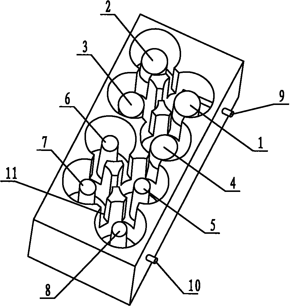
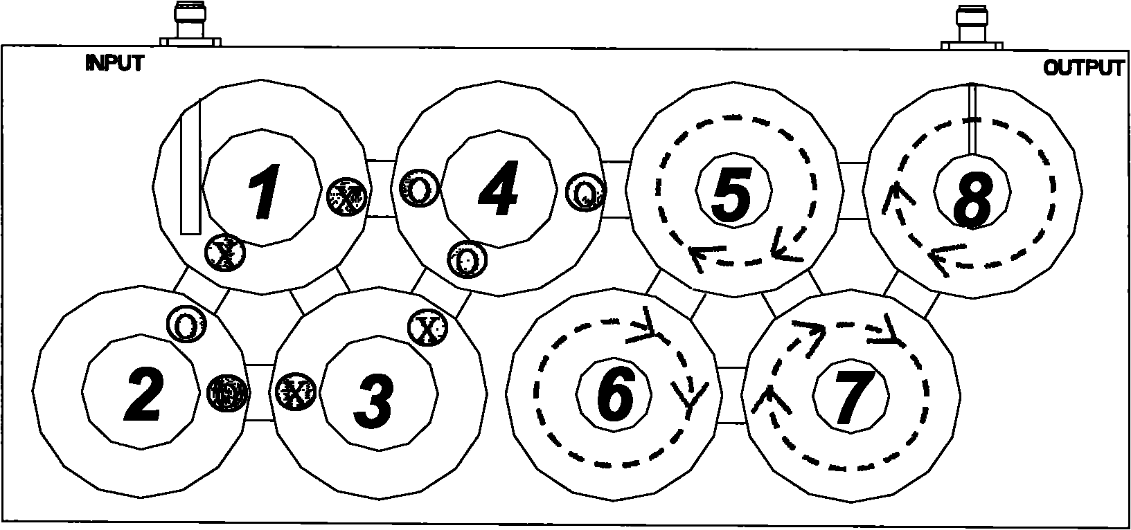
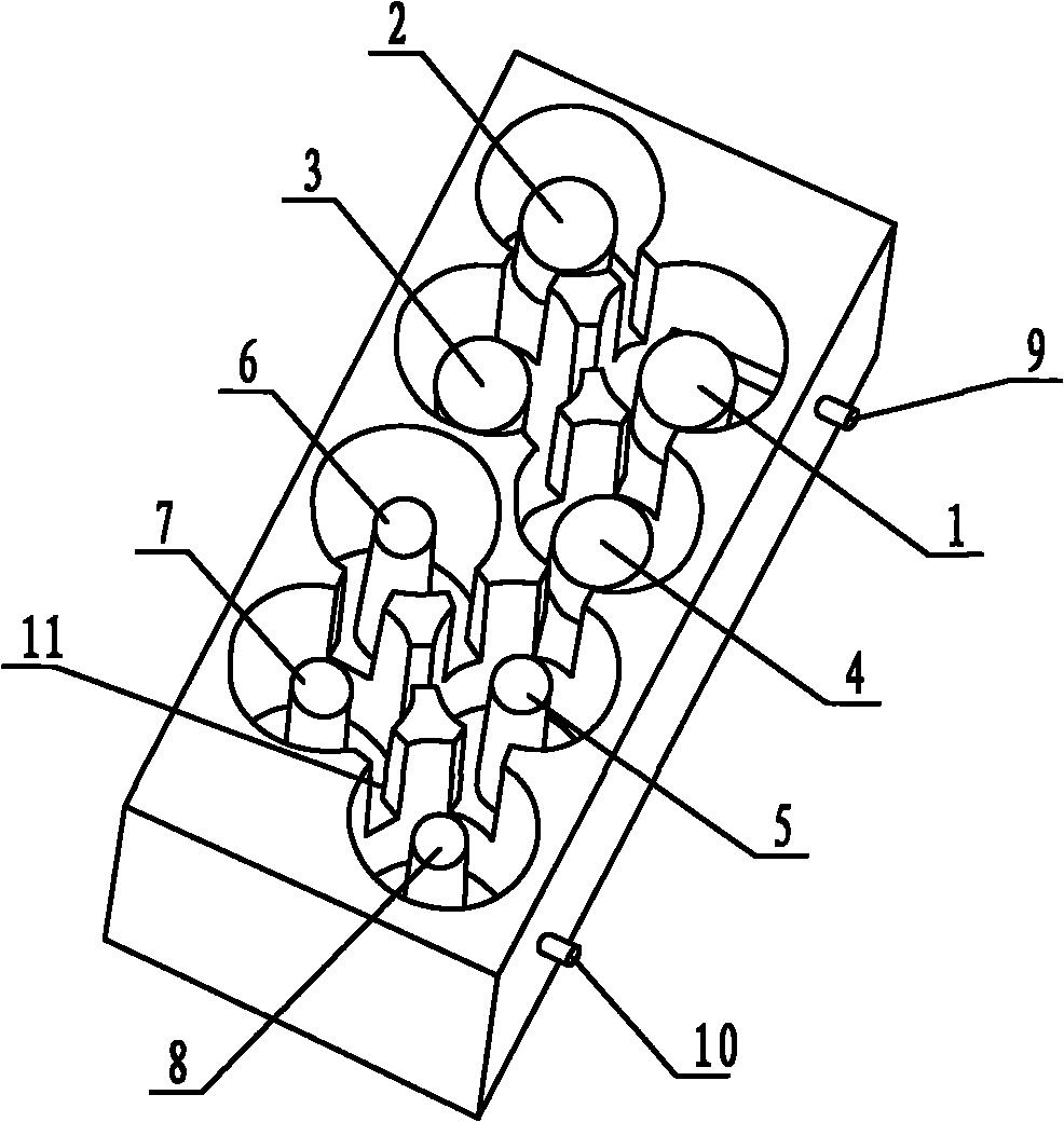
[0014] Such as figure 1 As shown, a schematic structural diagram of an 8-stage filter of the microwave filter of the present invention is given. 9 is the RF input connector for transmitting RF signals, 10 is the RF output connector for transmitting RF signals, all extending into the resonant cavity, and 11 is the Error! connection between the resonant cavities. Not a valid link., the floor plan of its realized physical structure is as follows figure 2 As shown, cavities 1 and 4 are Hz field coupling, for Hz field coupling, "+" indicates that the direction of the field is the direction of piercing the paper from the inside to the outside, and "o" indicates that the field is the direction of entering the paper from the outside to the inside; the cavity Body 5 and 8 are Hφ coupling, and the direction of the sword head indicates the direction of the magnetic field. The coupling magnetic field of cavity 1 to 4 can be synthesized by TE01 mode dielectric cavity, and the coupling m...
PUM
 Abstract
Description
Claims
Application Information