Rotating electrical machine and its manufacturing method

A technology for rotating electrical machines and rotating shafts, which is applied in the manufacture of stator/rotor bodies, electric components, electrical components, etc. It can solve the problems of increased amplitude of fundamental wave components and difficulty in achieving small and high output, and achieves increased amplitude and small size High output effect

Inactive Publication Date: 2011-04-13
YASKAWA DENKI KK
View PDF7 Cites 17 Cited by
  • Summary
  • Abstract
  • Description
  • Claims
  • Application Information

AI Technical Summary

Problems solved by technology

[0008] In this way, it is difficult to increase the amplitude of the fundamental wave component of the air-gap magnetic flux density in the conventional rotating electrical machine having the MFCSPM array, and it is difficult to realize miniaturization and high output

Method used


Image

  • Rotating electrical machine and its manufacturing method
  • Rotating electrical machine and its manufacturing method
  • Rotating electrical machine and its manufacturing method

Examples


no. 1 Embodiment approach

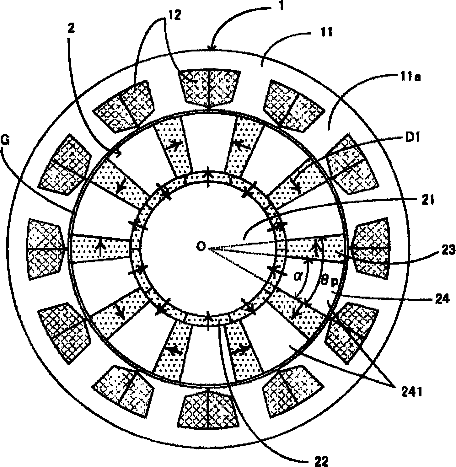
[0043] In the rotating electric machine according to the first embodiment of the present invention, the permanent magnets used in the rotor are arranged by an arrangement method called MMASPM (Magnetic Mate rial Attached Surface Permanent Magnet) arrangement. use figure 1 This arrangement will be specifically described.

[0044] figure 1 It is a cross-sectional view of the rotating electric machine according to the first embodiment. figure 1 The "O" shown indicates the axis of rotation of the rotor. figure 1 A cross section of the rotating electrical machine when the rotating electrical machine is cut perpendicular to the rotation axis O direction is shown. figure 1 The "G" shown is the air gap that exists between the rotor and stator. figure 1 The shown one-way arrow D1 indicates the magnetization direction of the permanent magnet.

[0045] exist figure 1 Among them, the rotating electric machine according to the first embodiment includes a stator 1 and a rotor 2 . The...

no. 2 Embodiment approach

[0085] refer to Figure 9 ~ Figure 11A , Figure 11B , the rotating electric machine according to the second embodiment including the rotor in consideration of manufacturability and mechanical strength will be described. Figure 9 It is a cross-sectional view of the rotating electric machine according to the second embodiment. Figure 10 yes Figure 9 A cross-sectional view of the rotor core shown. Figure 11 is Figure 9 Cutaway view of the rotor shown. Figure 11B is in Figure 11A Figures of end caps are added to the structure shown. Figure 9 ~ Figure 11A , Figure 11B The "O" shown indicates the axis of rotation of the rotor. Figure 9 A cross section of the rotating electrical machine when the rotating electrical machine is cut perpendicular to the rotation axis O direction is shown. Figure 10 shows a cut perpendicular to the direction of rotation axis O Figure 9 The section of the rotor core when the rotor core is shown. Figure 11A , Figure 11B shows the ...

no. 3 Embodiment approach

[0104] refer to Figure 12 ~ Figure 14A , Figure 14B , a rotating electric machine according to a third embodiment including a rotor in consideration of manufacturability and mechanical strength will be described. Figure 12 It is a cross-sectional view of the rotating electric machine according to the third embodiment. Figure 13 yes Figure 12 A cross-sectional view of the rotor core shown. Figure 14A yes Figure 12 Cutaway view of the rotor shown. Figure 14B is in Figure 14A Figures of end caps are added to the structure shown. Figure 12 ~ Figure 14A , Figure 14B The "O" shown indicates the axis of rotation of the rotor. Figure 12 A cross section of the rotating electrical machine when the rotating electrical machine is cut perpendicular to the rotation axis O direction is shown. Figure 13 shows a cut perpendicular to the direction of rotation axis O Figure 12 The section of the rotor core when the rotor core is shown. Figure 14A , Figure 14B shows th...


PUM


Abstract

This invention provides a rotating electrical machine which increases more easily an amplitude of a fundamental wave component in a gap magnetic flux density and realizes a small size high output. The rotating electrical machine including a rotor that has an even number of first permanent magnets aligned in a circumferential direction of the rotor, second permanent magnets of a number equal to that of the first permanent magnets, provided respectively between the stator and circumferential ends of the first permanent magnets adjacent to each other in the circumferential direction, and core pieces of a number equal to that of the first permanent magnets, provided respectively between the second permanent magnets adjacent to each other in the circumferential direction. Each of the first permanent magnets has a direction of magnetization in parallel with a radial direction of the rotor, the directions of magnetization of the first permanent magnets adjacent to each other in the circumferential direction are opposite to each other, each of the second permanent magnets has a direction of magnetization perpendicular to the radial direction, the directions of magnetization of the second permanent magnets adjacent to each other in the circumferential direction are opposite to each other, and the first permanent magnet and the two second permanent magnets which are adjacent to the core piece have magnetic poles identical to one another on ends facing the core piece.

Description

technical field [0001] The present invention relates to a rotating electrical machine and a manufacturing method thereof. Background technique [0002] A conventional rotating electric machine has proposed a technique for increasing the maximum value of a magnetic flux density in an air gap between a stator and a rotor (hereinafter referred to as air-gap magnetic flux density) (for example, refer to Patent Document 1). In Patent Document 1, the permanent magnets used in the rotor are arranged in an arrangement method called MFCSPM (Magnetic Flux Concentrated Surface Perma nent Magnet) arrangement. The arrangement will be described in detail below. [0003] The rotor includes a shaft, a rotor core, a first permanent magnet, and a second permanent magnet. The rotor core is arranged on the outer periphery of the rotating shaft. An even number of first permanent magnets is provided on the outer periphery of the rotor core. The first permanent magnets are arranged in parallel...

Claims


Application Information

Patent Timeline
Patent Type & Authority Applications(China)
IPC IPC(8): H02K1/27H02K1/22H02K15/03
CPCH02K1/2766
Inventor 村上宗司大户基道矢原春树西真一
Owner YASKAWA DENKI KK
Why Eureka
Try Eureka