Radio-frequency (RF) signal test connection structure and radio-frequency signal test optimization method

A technology of radio frequency signal and test connection, which is applied in the field of radio frequency signal test and radio frequency communication. It can solve the problems of poor cooperation between the radio frequency head and the antenna connector, increase the cost of product materials, and the inability to customize the fixture test, etc., so as to improve the pass-through rate of the test. , high test efficiency, cost-saving effect of antenna connector

Inactive Publication Date: 2011-04-13
SHANGHAI GONGJIN COMM TECH
View PDF5 Cites 12 Cited by
  • Summary
  • Abstract
  • Description
  • Claims
  • Application Information

AI Technical Summary

Problems solved by technology

[0004] (1) The product uses an antenna connector, which increases the cost of product materials;
[0005] (2) The RF connector for testing is easily damaged and the testing cost is high;
[0006] (3) The radio frequency head and the antenna connector often do not cooperate well, and the measurement error is high;
[0007] (4) Antenna connectors of some specifications do not have matching RF heads, and the production cannot be customized for fixture testing, and the efficiency is low

Method used


Image

  • Radio-frequency (RF) signal test connection structure and radio-frequency signal test optimization method
  • Radio-frequency (RF) signal test connection structure and radio-frequency signal test optimization method

Examples


Embodiment Construction

[0025] In order to understand the technical content of the present invention more clearly, the following examples are given in detail.

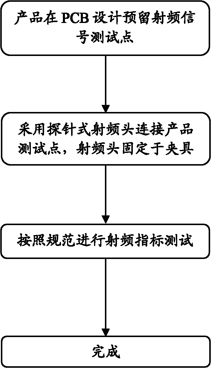
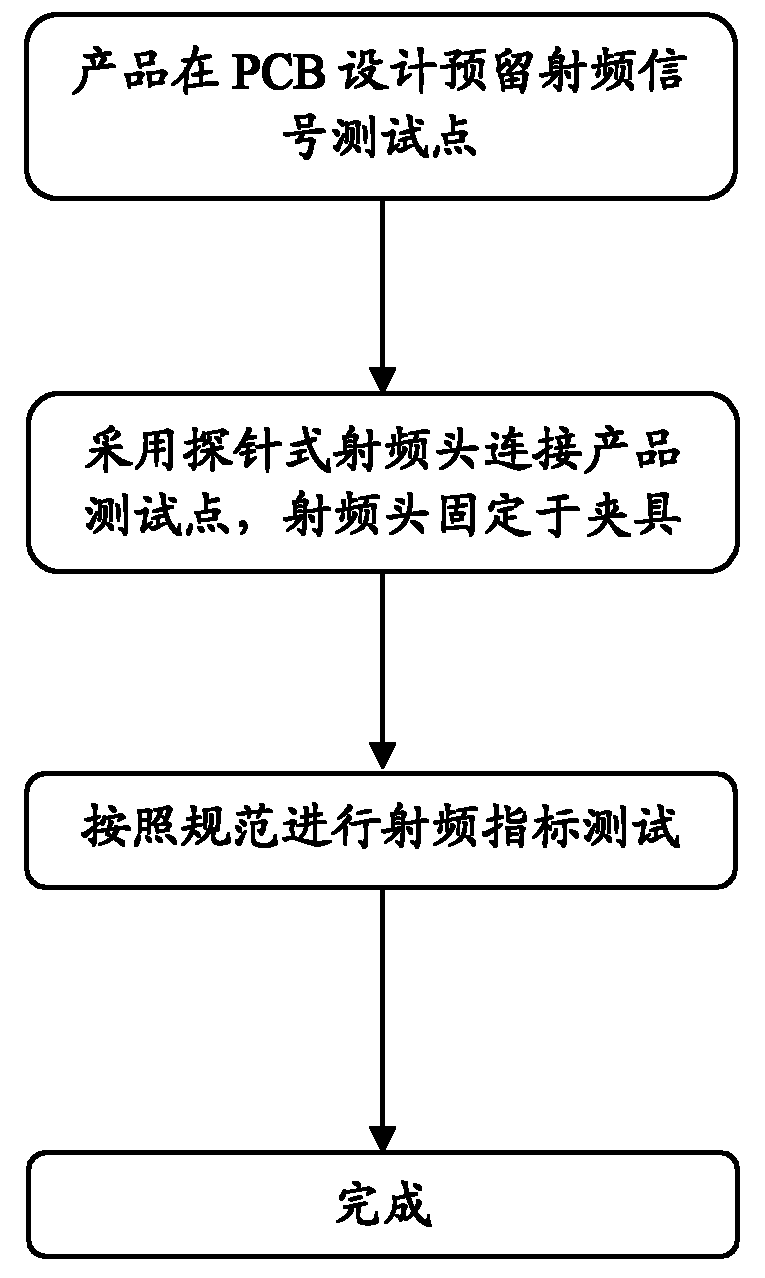
[0026] The radio frequency signal test connection structure includes a radio frequency test instrument, wherein a radio frequency signal test point is arranged on the product to be tested, and the radio frequency test instrument is connected with a probe type radio frequency head through a radio frequency cable, and the probe type The end probe of the radio frequency head is in contact with the radio frequency signal test point.

[0027] Wherein, the radio frequency signal test point is set on the opposite side of the antenna connector on the product under test, and the size of the radio frequency signal test point is the same as the contact surface size of the end probe of the probe type radio frequency head. Match, and the radio frequency signal test point is the radio frequency signal exposed copper part and the ground signal exposed coppe...


PUM


Abstract

The invention relates to a radio-frequency (RF) signal test connection structure, which comprises a radio-frequency tester, a tested product is provided with a radio-frequency signal test point, the radio-frequency tester is connected with a probe-type radio-frequency head by a radio-frequency cable, and a probe at the end part of the probe-type radio-frequency head is contacted and connected with the radio-frequency signal test point. The invention also relates to a method for realizing radio-frequency signal test optimization based on the radio-frequency signal test connection structure. The radio-frequency signal test connection structure and the radio-frequency signal test optimization method of the invention have the advantages that: the size of the test point is matched with the used probe-type radio-frequency head; the hardware test connection mode is as follows: an RF output port of the tester, the radio-frequency cable, the probe type radio-frequency head, and the radio-frequency signal test point of the tested product are sequentially connected, therefore, the cost for an antenna connector in a BOM of the tested product is saved; the probe-type radio-frequency head is not easy to be damaged, thereby reducing the test cost; the probe-type radio-frequency head is fixed on a clamp for testing, thereby improving the first pass yield of the tested product; meanwhile, the radio-frequency signal test connection structure and the radio-frequency signal test optimization method of the invention are high in test efficiency, simple in structure, fast and convenient to operate, stable and reliable in operating performance, and wide in application scope.

Description

technical field [0001] The invention relates to the field of radio frequency communication, in particular to the technical field of radio frequency signal testing, and specifically refers to a radio frequency signal test connection structure and a radio frequency signal test optimization method. Background technique [0002] Nowadays, radio frequency technology is widely used in various fields, such as: TV, radio, mobile phone, radar, automatic identification system, etc. Products designed with radio frequency functions must undergo a series of radio frequency index tests before delivery to meet product requirements. requirements. [0003] At present, most manufacturers in the industry use conduction testing in the mass production and testing of products, that is, the hardware connection method is: test instrument radio frequency (RF) port + RF cable + RF connector + product antenna connector. Then use software to control the instrument on the PC side for automated testing....

Claims


Application Information

Patent Timeline
Patent Type & Authority Applications(China)
IPC IPC(8): H04B17/00G01R31/02
Inventor 曹生法王浩
Owner SHANGHAI GONGJIN COMM TECH
Why Eureka
Try Eureka