Lighting device, display device, and television receiving device

A lighting device and an unconfigured technology, which is applied to the cooling/heating device of the lighting device, the lighting device, the components of the lighting device, etc., can solve the problems of increasing the number of lamps, failing to improve the brightness, and increasing the cost of the backlight source device.

Inactive Publication Date: 2011-04-13
SHARP KK
View PDF1 Cites 5 Cited by
  • Summary
  • Abstract
  • Description
  • Claims
  • Application Information

AI Technical Summary

Problems solved by technology

However, if the number of lamps is increased, the cost of the backlight device will be increased, and power consumption will also be increased
In addition, if the diffusion degree of the diffusion plate is increased, the brightness cannot be increased, and there is still a problem that the number of lamps needs to be increased.

Method used


Image

  • Lighting device, display device, and television receiving device
  • Lighting device, display device, and television receiving device
  • Lighting device, display device, and television receiving device

Examples


Embodiment approach 1

[0104] according to Figure 1 to Figure 8 Embodiment 1 of the present invention will be described.

[0105] First, the configuration of a television receiver TV including a liquid crystal display device 10 will be described.

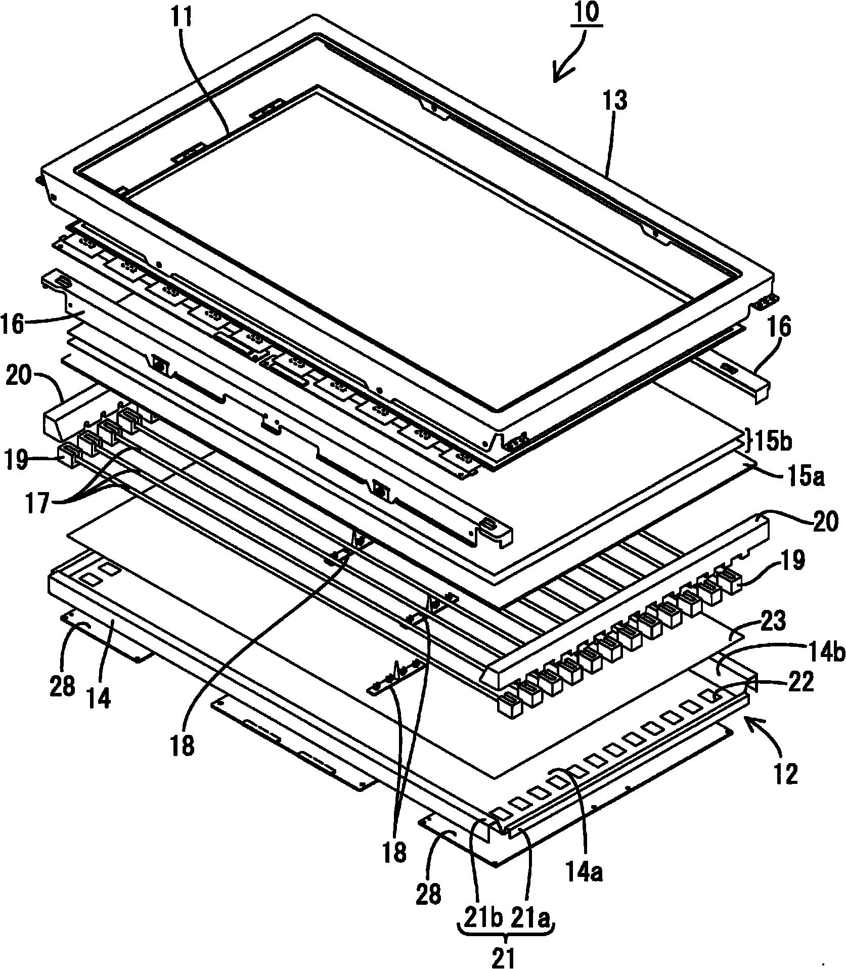
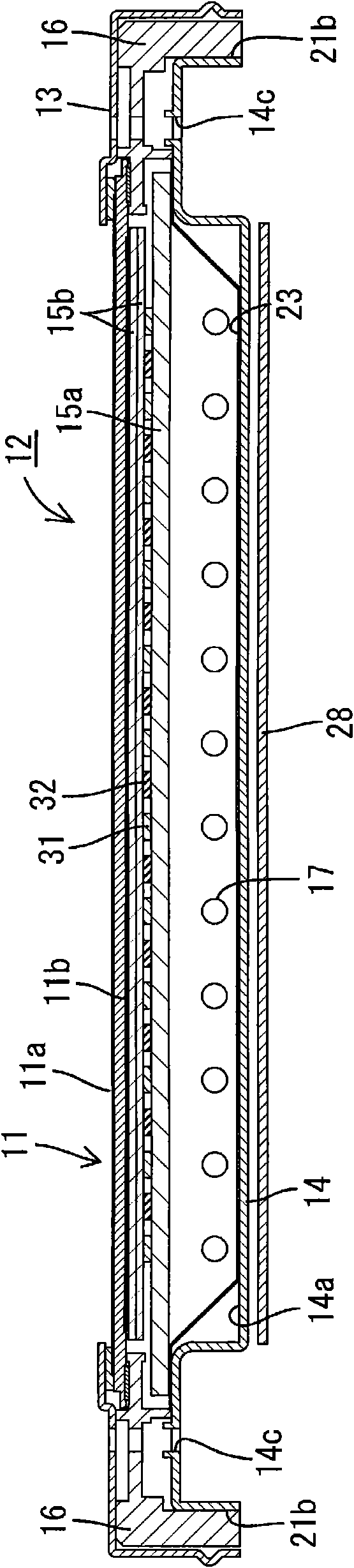
[0106] figure 1 It is an exploded perspective view showing a schematic configuration of a television receiving device according to this embodiment, figure 2 yes means figure 1 An exploded perspective view of the schematic structure of the liquid crystal display device included in the TV receiving device of image 3 is to mean along figure 2 A cross-sectional view of the cross-sectional structure in the short-side direction of the liquid crystal display device, Figure 4 is to mean along figure 2 A cross-sectional view of the cross-sectional structure of the liquid crystal display device in the longitudinal direction, Figure 5 is expressed in figure 2 A plan view of the arrangement structure of the cold cathode tube and the chassis included...

Embodiment approach 2

[0170] Below, according to Figure 16 to Figure 20 Embodiment 2 of the present invention will be described. The difference from Embodiment 1 above is that the arrangement structure of the cold cathode tubes is changed, and the others are the same as Embodiment 1 above. The same reference numerals are assigned to the same parts as those in the above-mentioned embodiment, and overlapping descriptions will be omitted.

[0171] Figure 16 is a cross-sectional view showing a cross-sectional structure along the short-side direction of the liquid crystal display device of this embodiment, Figure 17 is expressed in Figure 16 A plan view of the arrangement structure of the cold cathode tube and the chassis included in the liquid crystal display device of .

[0172] There are a plurality of cold-cathode tubes 17, and they are partially accommodated in the base 14 in a state of being arranged parallel to each other at relatively small intervals. More specifically, as Figure 16 w...

Embodiment approach 3

[0224] Below, according to Figure 31 to Figure 33 Embodiment 3 of the present invention will be described. In this third embodiment, the arrangement of the cold cathode tubes and the structure of the light guide plate are changed, and the rest are the same as the above-mentioned embodiment. The same reference numerals are assigned to the same parts as those in the above-mentioned embodiment, and overlapping descriptions will be omitted.

[0225] Figure 31 It is a plan view showing the arrangement structure of cold cathode tubes and chassis included in the liquid crystal display device of this embodiment, Figure 32 It is a plan view illustrating the distribution of light reflectance in the entire second surface of the light guide plate included in the liquid crystal display device, Figure 33 is expressed in Figure 32 Graph of the variation of light reflectance in the short-side direction of the light guide plate. In addition, in Figure 31 to Figure 33 , let the long...


PUM

PropertyMeasurementUnit
reflectanceaaaaaaaaaa

Abstract

A lighting device (12) is characterized by being provided with a light source (17), a chassis (14) housing the light source (17) and provided with an opening (14b) for emitting light of the light source (17), and an optical member (15a) disposed so as to face the light source (17) and cover the opening (14b), wherein the optical member (15a) is formed of a member with a substantially uniform light transmittance and provided with a first plane (30a) facing the light source (17) and a second plane (30b) located on the side opposite thereto, a light reflection portion (31) for reflecting light from the first plane (30a) side is formed in a region overlapping with the light source (17) in plan view of the second plane (30b) of the optical member (15a), and a light scattering portion (32) for scattering the light is formed in a region not overlapping with the light source (17) in plan view of the optical member (15a).

Description

technical field [0001] The present invention relates to an illuminating device, a display device and a television receiving device. Background technique [0002] For example, a liquid crystal panel used in a liquid crystal display device such as a liquid crystal television requires a backlight device as an illumination device because it does not emit light by itself. This backlight unit is installed on the rear side of the liquid crystal panel (the side opposite to the display surface), which is known, and includes: a chassis having an opening in the surface on the side of the liquid crystal panel; A cold cathode tube and a diffusion plate arranged in the opening of the base to efficiently emit the light emitted by the fluorescent tube to the liquid crystal panel side. [0003] This backlight device has a structure in which, when a fluorescent tube emitting linear light is used as a fluorescent tube, a plurality of fluorescent tubes are arranged, and optical components are ...

Claims


Application Information

Patent Timeline
Patent Type & Authority Applications(China)
IPC IPC(8): F21S2/00F21V3/00F21V7/00F21V29/00G02F1/1333G09F9/00F21Y103/00G02F1/13357
CPCG02F1/133606G02F1/133604G02F1/133611
Inventor 鹰田良树
Owner SHARP KK
Why Eureka
Try Eureka