Supercharge Your Innovation With Domain-Expert AI Agents!

LED fluorescent lamp

A technology of LED fluorescent lamps and LED light sources, applied in lampshades, light sources, electric light sources, etc., can solve problems such as poor heat dissipation, high local temperature, hot hands, etc., achieve good heat dissipation effects, enhance stability, and reduce temperature.

Inactive Publication Date: 2013-04-10
MASS TECH (HK) LTD
View PDF1 Cites 0 Cited by
  • Summary
  • Abstract
  • Description
  • Claims
  • Application Information

AI Technical Summary

Problems solved by technology

Although the LED array structure can meet the lighting requirements, it also produces problems such as heat concentration, excessive local temperature, and affecting the stability of the circuit control system.
Since there is no special heat conduction and heat dissipation device, the heat generated by multiple LED light sources cannot be effectively dissipated, so that the temperature of the shell of the lamp will be relatively high, and there will be a danger of scalding when people touch it; moreover, the temperature High also makes the lamp more susceptible to damage
[0004] At present, many technical solutions have been proposed to solve the heat dissipation problem of LED lamps, but some of these technical solutions have poor heat dissipation effects, and some have good heat dissipation effects, but the cost is too high and the structure is complicated.
For example, China's invention patent application number 200910011246.8, the patent application titled "Loop-type heat pipe radiator heat dissipation LED lighting lamp", discloses a LED lighting lamp that uses a loop-type heat pipe radiator to dissipate heat. The principle of small thermal resistance and high thermal conductivity of the radiator solves the problem of LED heat dissipation, but this heat dissipation method is costly and complex in structure

Method used


Image

  • LED fluorescent lamp
  • LED fluorescent lamp
  • LED fluorescent lamp

Examples


Embodiment Construction

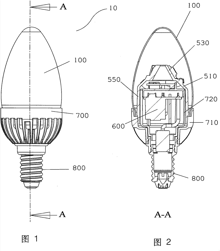
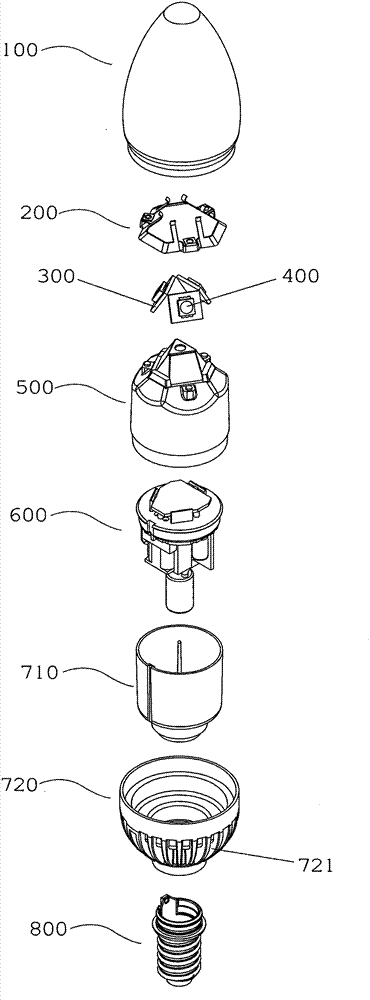
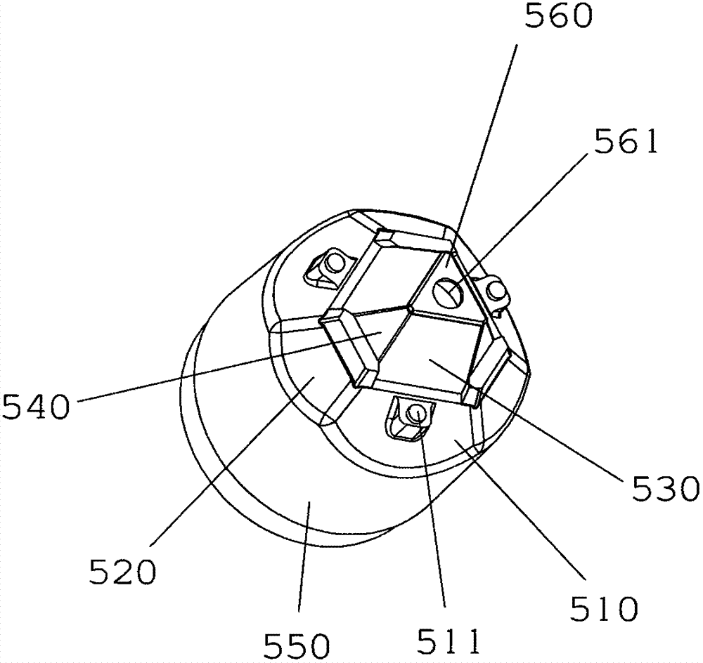
[0031] refer to Figure 1 to Figure 3 , the figure shows an LED fluorescent lamp 10 as a preferred embodiment of the present invention, the fluorescent lamp 10 includes a glass bulb 100, three LED light sources 400, three light source panels 300, a heat conducting device 500, a control circuit 600, and a rear cover 700 And the lamp head 800.

[0032] The glass bubble 100 can be a transparent glass bubble, or a glass bubble sprayed with silica gel, a twisted glass bubble, a frosted glass bubble, etc. can be selected as required. The lamp holder 800 can be designed as lamp holders of various sizes as required, such as E11, E12, E14, E17, E26, E27 and so on. The control circuit 600 is not the main point of the present invention, and will not be described in detail here.

[0033] The LED light source can consist of one or more LEDs. In this embodiment, each of the three LED light sources 400 is composed of three chip LEDs, which are respectively fixed on three light source pane...


PUM


Abstract

The invention provides a LED fluorescent lamp (10), comprising a lamp cap (800), a bulb shell (100), a control circuit (600), at least two LED light sources (400), at least two light source panels (300) on which the at least two LED light sources are secured, respectively, heat-conducting means (500) and cover (700) means. The heating-conducting means (500) comprises at least two thermally conductive base plates which are disposed at an angle oblique to a longitudinal central axis of the heat-conducting means, and on which base plates the at least two light source panels are secured in a thermally conductive manner, the base plates extending downward from their bottom ends to form a receiving chamber. The cover means (700) comprises a casing, and a hollow barrel (710) for accommodating the control circuit, the casing is engaged snugly with the heat-conducing means such that the heat-conducting means is coupled thermally to the cover means. The cover means have a plurality of radiating fins (721) on its outer surface. A path having good thermal conduction and thermal dissipation is created along the light source panels - the heat-conducting means ۥ the casing of the cover means ۥ the radiating fins. The LED fluorescent lamp exhibits excellent thermal conduction and thermal dissipation to provide a solution to the problem associated with the thermal dissipation of the LEDs.

Description

technical field [0001] The invention relates to the field of lighting fixtures. More specifically, the present invention relates to an LED fluorescent lamp used as a lighting fixture, the LED fluorescent lamp has high luminous efficiency and good heat dissipation. Background of the invention [0002] As a solid light source with great development potential, LED has attracted more and more attention due to its advantages of long life, firm structure, low power consumption and flexible shape and size since its birth in the 1960s, and has gradually replaced Traditional high-voltage halogen lamps are used in various lighting fields. However, the LED lamp itself generates a relatively large amount of heat when it is working, resulting in a large light attenuation and shortening the service life of the LED lamp, thus limiting the application range of the LED lamp in the lighting field to a certain extent. [0003] Because the brightness and power of a single LED light source are...

Claims


Application Information

Patent Timeline
Patent Type & Authority Patents(China)
IPC IPC(8): F21S8/00F21V17/00F21V19/00F21V23/00F21V29/00F21Y101/02
CPCF21V29/2225F21V3/049F21V23/02F21Y2101/02Y02B20/386F21K9/00F21V29/004F21K9/135F21Y2111/007F21V3/0418F21K9/232F21V3/061F21V29/77F21V29/83F21Y2107/40F21Y2115/10
Inventor 胡安华
Owner MASS TECH (HK) LTD
Features
  • R&D
  • Intellectual Property
  • Life Sciences
  • Materials
  • Tech Scout
  • Unparalleled Data Quality
  • Higher Quality Content
  • 60% Fewer Hallucinations
Learn More