
Multilayer inductor and method for manufacturing the same

A technology of laminated inductors and manufacturing methods, applied in chemical instruments and methods, inductors, printed inductors, etc., can solve the problems of easy cracks, difficulty in simultaneous firing of internal conductors, deterioration of product temperature characteristics, etc. Less fluctuation, good DC overlap characteristics, stable production effect

Inactive Publication Date: 2011-04-13
TAIYO YUDEN KK
View PDF3 Cites 15 Cited by
  • Summary
  • Abstract
  • Description
  • Claims
  • Application Information

AI Technical Summary

Problems solved by technology

Therefore, depending on the temperature, the apparent thickness of the non-magnetic layer changes, so there is a problem that the temperature characteristics of the product deteriorate
[0009] In addition, as described in Patent Document 2, as the ceramics constituting the nonmagnetic layer, for example, TiO 2 , due to TiO 2 The firing temperature of Ni-Zn is higher than the melting point of Ag, so it is difficult to fire simultaneously with the internal conductor composed of Ag, or cracks are likely to occur at the interface with Ni-Zn-Cu ferrite. Therefore, when using Ni-Zn - Difficult to use TiO in case of Cu ferrite as magnetic layer 2

Method used


Image

  • Multilayer inductor and method for manufacturing the same
  • Multilayer inductor and method for manufacturing the same
  • Multilayer inductor and method for manufacturing the same

Examples


Embodiment

[0065] Hereinafter, the present invention will be described in further detail through implementation examples.

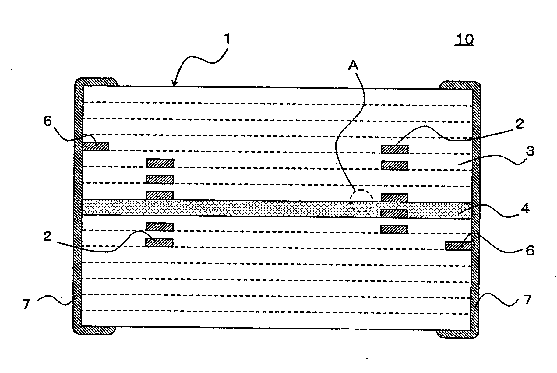
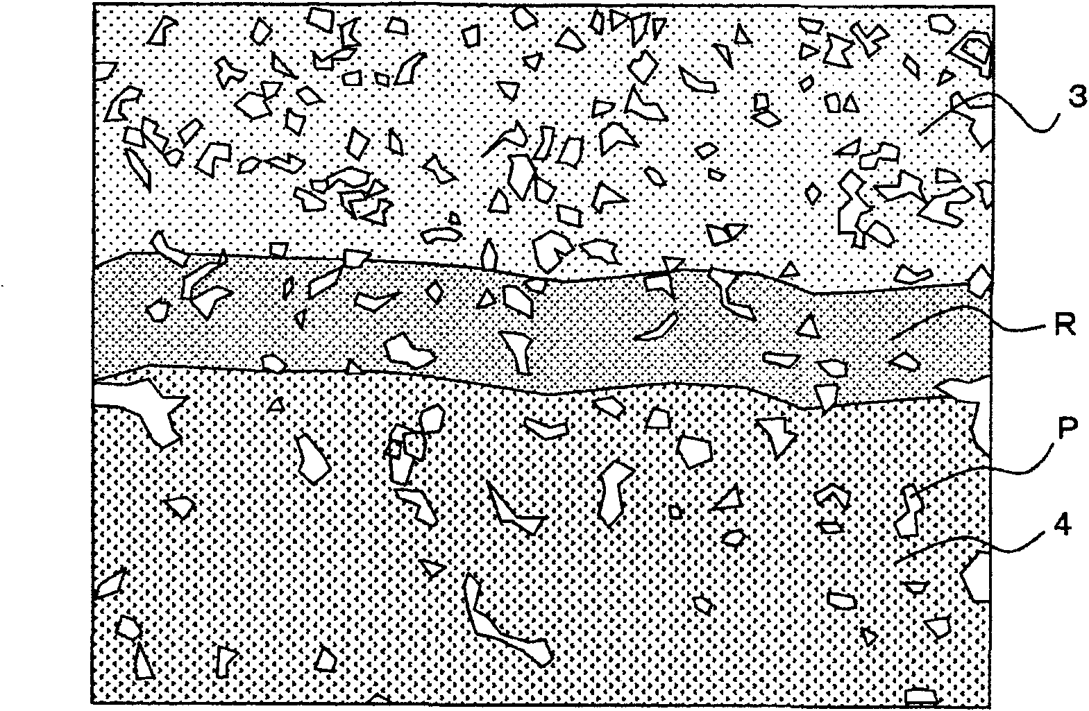
[0066] Add ethanol (solvent) and PVA-based binder to the Ni-Zn-Cu ferrite powder of the composition shown in Table 1, mix it, apply it on a PET film, and obtain a magnetic material sheet (magnetic material layer) . In addition, as shown in Table 1, in TiO 2 Main component and contains NiO, CuO, Mn 3 o 4 and ZrO 2 Dielectric powder (called "TiO 2Low-temperature firing material") powder was added and mixed with the same solvent and binder, and coated on a PET film to obtain a non-magnetic sheet (non-magnetic layer).

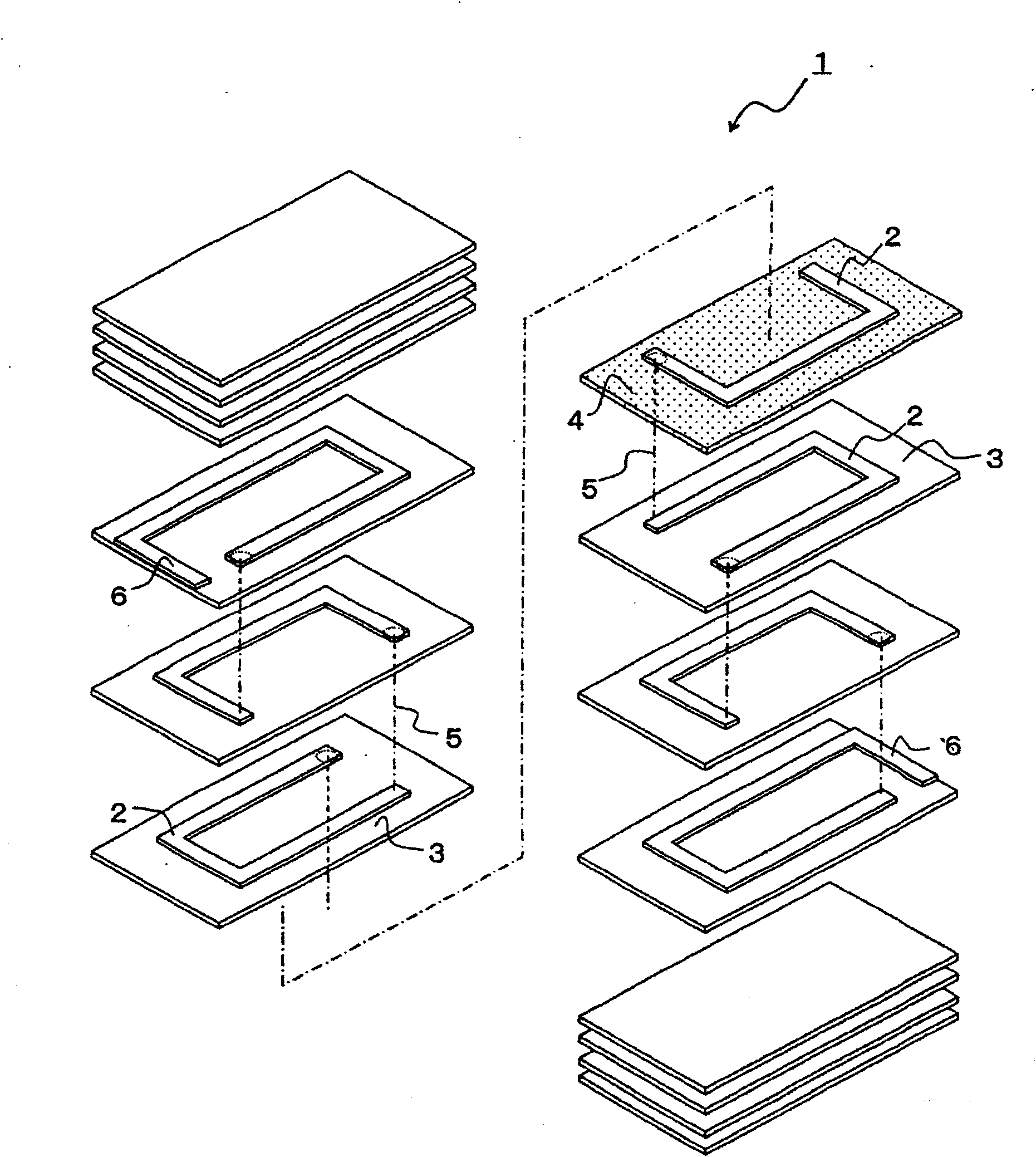
[0067] Electrodes (conductor layers for U-shaped coils) are printed on the obtained green sheet (Grinsite), and laminated to produce such as figure 2 Structured sheet laminates (TiO 2 The laminated body of the example of the low-temperature firing material), and the obtained sheet laminated body was cut into unit sizes to obtain a sheet-shaped un...


PUM


Abstract

Disclosed is a multilayer inductor using an Ni-Zn-Cu ferrite, which has improved temperature characteristics and is free from structural defects. A method for manufacturing the multilayer inductor is also disclosed. The multilayer inductor is characterized by comprising: a multilayer body (1) having a rectangular solid shape, which comprises a plurality of magnetic layers (3, 3) composed of an Ni-Zn-Cu ferrite, a plurality of conductive layers (2, 2) forming a coil by being laminated via the magnetic layers, and at least one non-magnetic layer (4) so formed as to be in contact with the plurality of magnetic layers (3, 3) and composed of a Ti-Ni-Cu-Mn-Zr dielectric; and at least a pair of external electrodes (7, 7) arranged on the ends of the multilayer body (1) and electrically connected to the ends of the coil.

Description

technical field [0001] The present invention relates to a laminated inductor (inductor, inductor), and in particular to a laminated power choke coil for a DC / DC converter. Background technique [0002] In a power choke coil for a power supply such as a DC / DC converter, there is an overlap characteristic as an important product characteristic. [0003] In the laminated power choke coil, a method of simultaneously firing the non-magnetic layer and the magnetic layer at the place where the magnetic flux is concentrated is used to suppress magnetic saturation and improve the overlapping characteristics. [0004] As one of such methods, Patent Documents 1 and 2 describe making the nonmagnetic layer, for example, Zn—Cu ferrite whose constituent elements are close to Ni—Zn—Cu ferrite constituting the magnetic layer. [0005] In addition, Patent Document 3 describes that ZnFe 2 o 4 、TiO 2 、WO 2 、 Ta 2 o 5 , cordierite-based ceramics, BaSnN-based ceramics, and CaMgSiAlB-based ...

Claims


Application Information

Patent Timeline
Patent Type & Authority Applications(China)
IPC IPC(8): H01F17/00H01F41/04
CPCH01F1/344H01F2017/002C04B2235/3284H01F17/0013H01F3/10B32B18/00C04B2235/3281C04B2235/6025H01F2017/0066H01F3/14C04B2235/3263C04B2235/3279C04B35/265C04B2237/34C04B2237/346C04B2235/3244C04B35/46Y10T29/4902
Inventor 中岛启之冈部健次野木谦一郎上山义明小林朋美冲野善和
Owner TAIYO YUDEN KK
Learn More