Vibration electric hammer

A technology of electric hammer and transmission piston, which is applied in the field of electric hammer and vibration electric hammer, which can solve the problems of complex structure, low service life, and large hand vibration, and achieve the effect of simple overall structure, long service life and small hand vibration

Inactive Publication Date: 2011-04-20
韩圣才
View PDF0 Cites 9 Cited by
  • Summary
  • Abstract
  • Description
  • Claims
  • Application Information

AI Technical Summary

Problems solved by technology

[0003] The purpose of the present invention is to provide a vibrating electric hammer, which overcomes the existing problems of the existing electric hammer, such as complex structure, easy damage to the electric hammer transmission mechanism, low service life, large hand vibration, easy fatigue and low noise. Big, easy to pollute the environment defects

Method used


Image

  • Vibration electric hammer
  • Vibration electric hammer

Examples


Embodiment Construction

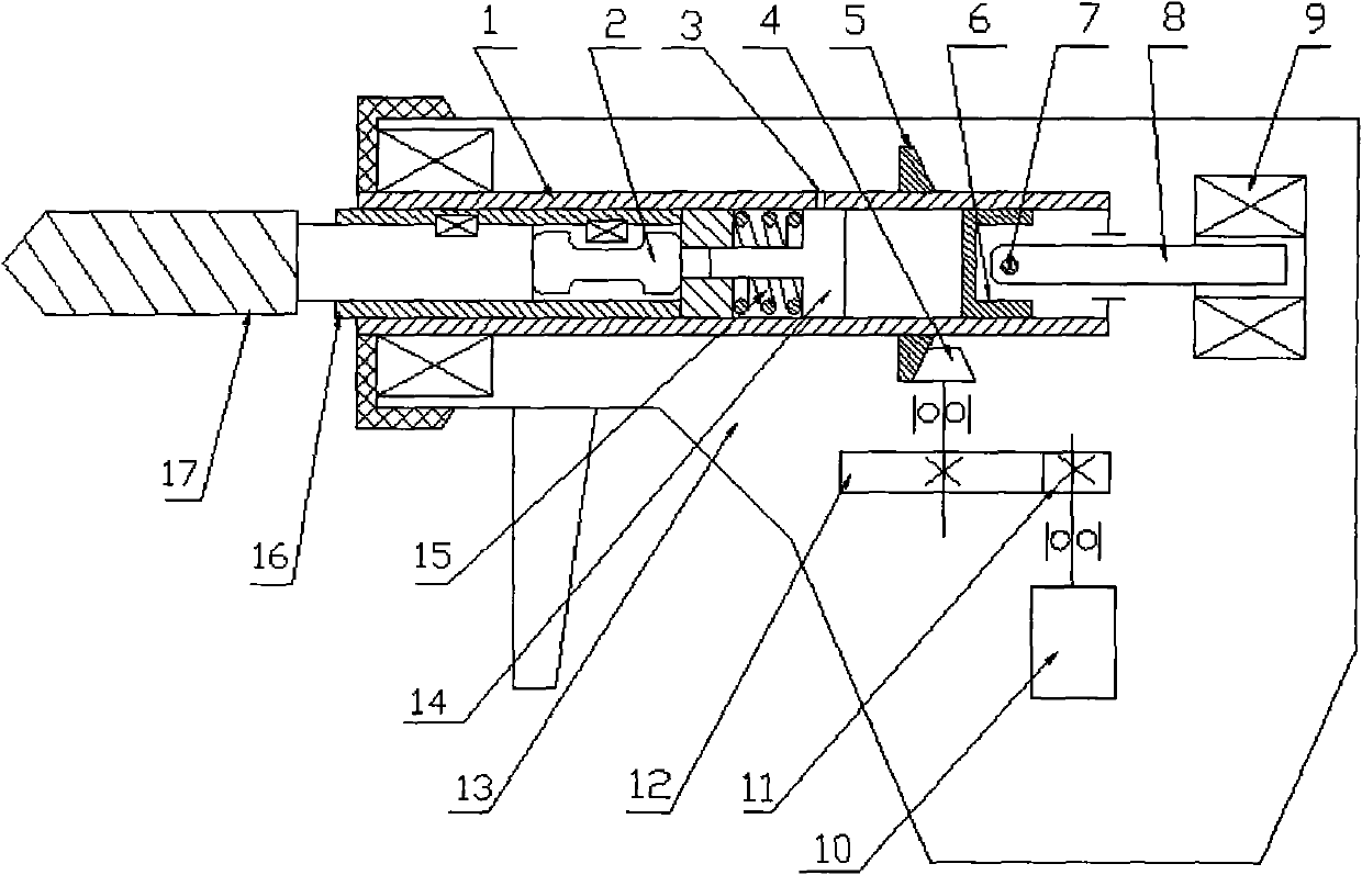
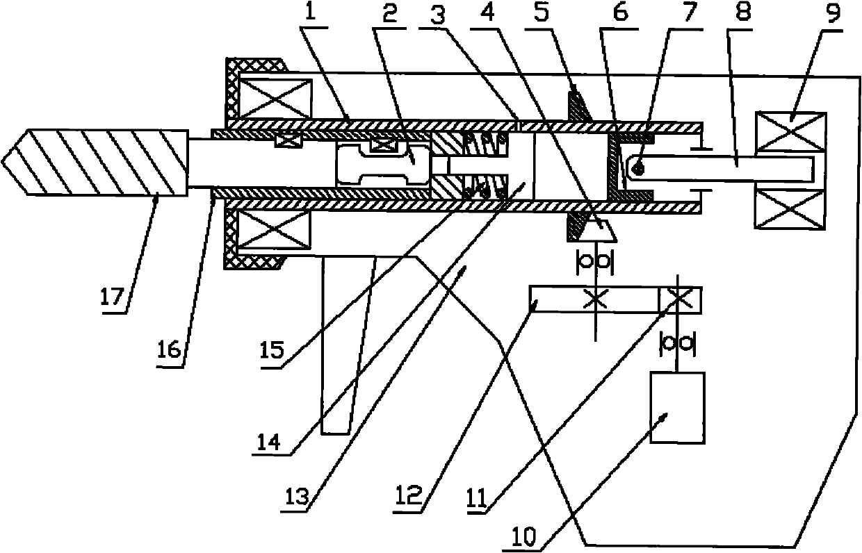
[0010] Install the fixed drill bushing (16) at the front end of the cylinder body (1), install the percussion hammer (2) at an appropriate position at the rear of the drill bushing (16), and install a compression spring ( 15), and install the transmission piston (14) together with the compression spring (15) inside the cylinder (1) at the rear of the drill sleeve (16), and the air hole (3) is opened outside the cylinder (1) On the top of the circle, the transmission piston (14) can just seal the air hole (3) in a free state; the large bevel gear (5) is installed and fixed on the appropriate position of the cylinder body (1), and the large bevel gear (5) and the small bevel gear Bevel gear (4), gear wheel (12), pinion gear (11), motor (10) form the relation of transmission chain successively; Rod iron core (8) links to each other with piston (6) by bearing pin (7), and electromagnet (9) is installed and fixed in the housing of appropriate position of cylinder body rear portion....


PUM


Abstract

The invention provides a vibration electric hammer, wherein a drill sleeve is fixedly mounted at a front end of a cylinder body; an impacting hammer is mounted on a proper position on a rear part of the drill sleeve; a compression spring is mounted the proper position of a drive piston; the drive piston and the compression spring are mounted in the cylinder body at the back of the drill sleeve; an air hole is arranged on an upper surface of an outer circle of the cylinder body; the drive piston can seal the air hole at a free state; large bevel gears are fixedly mounted at the proper position of the cylinder body; the large bevel gears, small bevel gears, large gears, small gears and a motor sequentially form a drive chain relationship; the piston is mounted at the proper position at the back of the cylinder body; a connecting rod iron core is connected with the piston via a pin shaft; and an electromagnet is fixedly mounted in a shell at the proper position at the back of the cylinder body.

Description

technical field [0001] The invention relates to an electric hammer, in particular to a vibrating electric hammer, which belongs to the technical field of electric tools. Background technique [0002] Because the vibrating electric hammer can generate a certain vibration impact force while drilling, it has a good drilling and cutting effect for some difficult-to-drill materials. At present, the principle of the impact force of the vibrating electric hammer is to rely on high-speed rotation This method of using mechanical impact to generate impact force has the following disadvantages: first, the structure is complicated due to the need for a corresponding mechanical transmission mechanism; secondly, due to the mechanical impact The force acts on the cam and the transmission mechanism, so the electric hammer transmission mechanism is easily damaged and the service life is low; again, because the cam has a certain amount of eccentricity when rotating, the hand feels a large vib...

Claims


Application Information

Patent Timeline
IPC IPC(8): B23B45/16B25D16/00
Inventor 韩圣才
Owner 韩圣才
Why Eureka
Try Eureka