Simulation alternating current electric locomotive
An electric locomotive and simulation technology, applied in the field of vehicles, to achieve the effect of improving reliability, overcoming complex wiring, and optimizing design parameters of real vehicles
- Summary
- Abstract
- Description
- Claims
- Application Information
AI Technical Summary
Problems solved by technology
Method used
Image
Examples
Embodiment 1
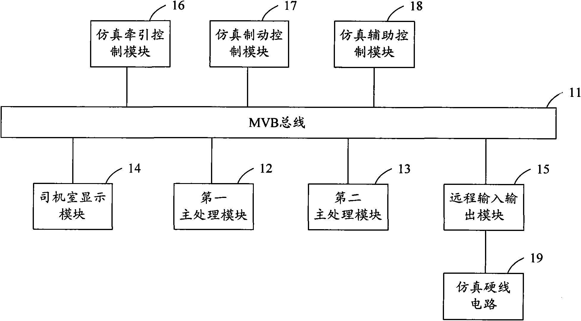
[0023] figure 1 It is a structural schematic diagram of Embodiment 1 of the simulated AC electric locomotive of the present invention. Such as figure 1 As shown, the simulated AC electric locomotive in the embodiment of the present invention includes: a first main processing module 12 connected to the MVB bus 11, a second main processing module 13, a driver's cab display module 14, a remote input and output module 15, and a simulated traction control module 16. Simulation braking control module 17 and simulation auxiliary control module 18.
[0024] The multifunction vehicle bus (Multifunction Vehicle Bus, MVB for short) based on distributed control has the advantages of strong real-time performance and high reliability. The above modules are respectively connected to the MVB bus, and information is transmitted and exchanged through the MVB bus, forming a complete communication network.
[0025] The first main processing module 12 is used for managing the MVB bus and contro...
Embodiment 2
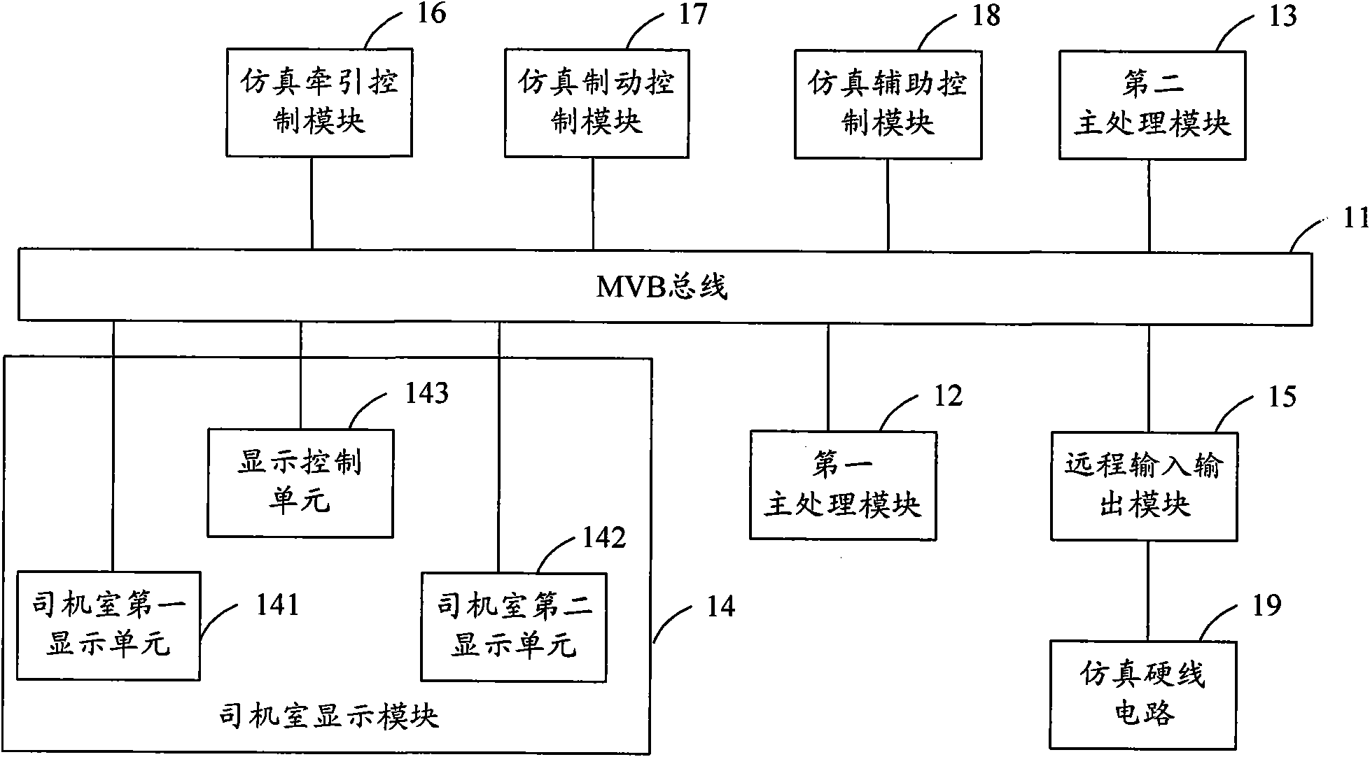
[0035] figure 2 It is a schematic structural diagram of Embodiment 2 of the simulated AC electric locomotive of the present invention. Such as figure 2 shown in figure 1 On the basis of , the cab display module 14 includes: a first cab display unit 141 , a cab second display unit 142 and a display control unit 143 respectively connected to the MVB bus 11 .
[0036]The display control unit 143 is used to forward the state information sent by the first main processing module 12 to the first display unit 141 of the driver's cab when it is determined that the first display unit 141 of the driver's cab is in the working state; When 141 is in a fault state, the state information sent by the first main processing module 12 is forwarded to the second display unit 142 of the driver's cab for display.
[0037] The display control unit 143 is also used to forward the user instruction received by the second display unit 142 of the driver's cab to the first main processing module when...
Embodiment 3
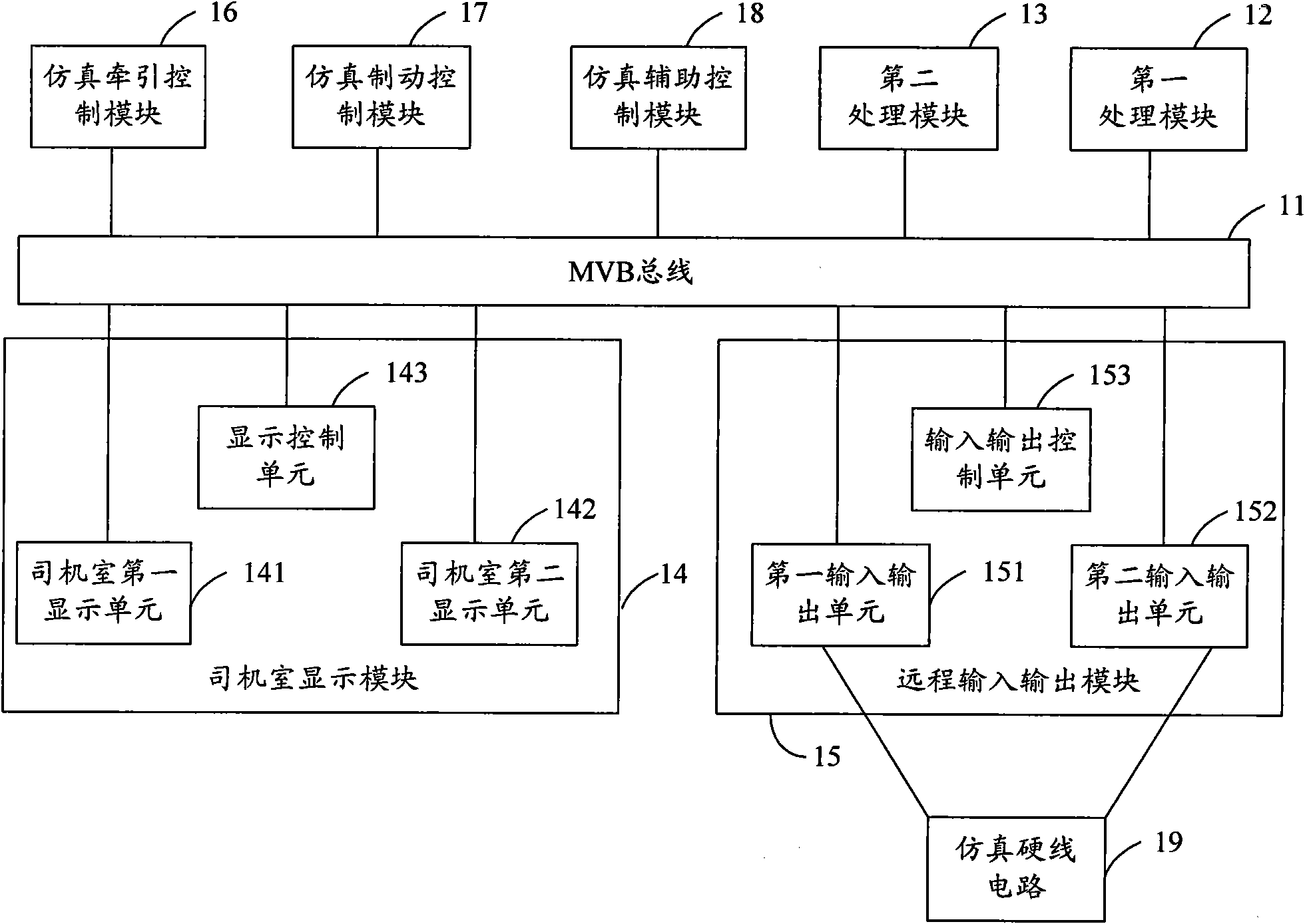
[0043] image 3 It is a structural schematic diagram of Embodiment 3 of the simulated AC electric locomotive of the present invention. Such as image 3 shown in figure 1 or figure 2 On the basis of , the remote input and output module 15 includes a first input and output unit 151 , a second input and output unit 152 and an input and output control unit 153 respectively connected to the MVB bus.
[0044] The first input and output unit 151 and the second input and output unit 152 are also respectively connected to the simulated hardwired circuit 19 for collecting state information of the simulated hardwired circuit 19 .
[0045] The input and output control unit 153 is used to send the state information of the simulated hard-wired circuit collected by the first input and output unit 151 to the first main processing module when determining that the first input and output unit 151 is in a working state; When the I / O unit 151 is in a non-working state, it sends the status inf...
PUM
 Abstract
Description
Claims
Application Information
 - R&D
- Intellectual Property
- Life Sciences
- Materials
- Tech Scout
- Unparalleled Data Quality
- Higher Quality Content
- 60% Fewer Hallucinations
Browse by: Latest US Patents, China's latest patents, Technical Efficacy Thesaurus, Application Domain, Technology Topic, Popular Technical Reports.
© 2025 PatSnap. All rights reserved.Legal|Privacy policy|Modern Slavery Act Transparency Statement|Sitemap|About US| Contact US: help@patsnap.com


