External cavity semiconductor laser

A semiconductor and laser technology, applied in the direction of semiconductor lasers, lasers, laser parts, etc., can solve the problems of small continuous non-mode-hopping laser frequency tuning range, etc., and achieve the effect of easy tuning and control, and frequency stability.

Inactive Publication Date: 2011-04-20
NAT INST OF METROLOGY CHINA
View PDF1 Cites 6 Cited by
  • Summary
  • Abstract
  • Description
  • Claims
  • Application Information

AI Technical Summary

Problems solved by technology

Generally speaking, the above-mentioned changes are not synchronous, which will cause the mode-hopping change of the laser mode, interrupting the tu

Method used


Image

  • External cavity semiconductor laser
  • External cavity semiconductor laser
  • External cavity semiconductor laser

Examples


Embodiment Construction

[0036] In order to make the object, technical solution and advantages of the present invention clearer, the present invention will be described in further detail below in conjunction with specific embodiments and with reference to the accompanying drawings.

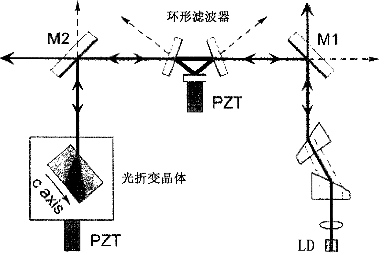
[0037] The external cavity semiconductor laser of the present invention mainly includes: a semiconductor laser tube (LD) 1, a collimator lens 3, a photorefractive crystal 14 and a monolithic annular F-P cavity (MFC) 5.

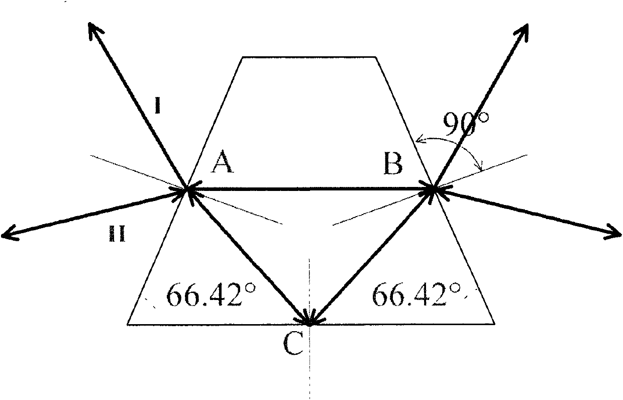
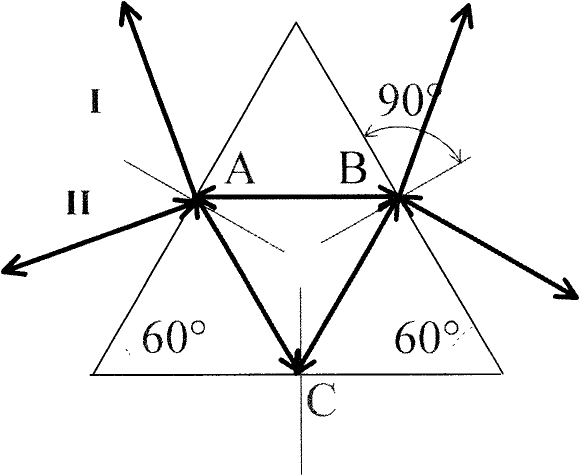
[0038] An example of the present invention is Figure 5 As shown, the light emitted by LD1 is collimated by the collimating lens 3, then passes through the half-wave plate (HW) 501, and the point A on the light input surface enters the single ring F-P cavity 5, and passes through the reflection plate coated with a high reflection film. After being reflected at point B on the surface, it goes to point C, and returns to point A after being totally reflected by the plane where point C is located, forming an ...


PUM


Abstract

The present invention discloses an external cavity semiconductor laser, comprising a semiconductor laser tube, a monoblock annular F-P cavity and a photorefractive crystal. The laying of each part in the semiconductor laser allows that: a light beam emitted from the semiconductor laser tube enters into the monoblock annular F-P cavity through an input surface of the monoblock annular F-P cavity, and is returned to the incidence point in the input surface after being reflected by at least two reflecting surfaces; and a transmitted light through one of the reflecting surfaces of the monoblock annular F-P cavity, which is made as an emergent light of the monoblock annular F-P cavity, enters into the photorefractive crystal, and is fed back to the semiconductor laser tube according to the original route. The present invention can realizes an output-stabilized narrow line width and a single-mode wide range of tune, simultaneously solves the problem that the stability of a discrete element F-P cavity is not good and vulnerable to outside interference, the volume of the F-P cavity is too large, and the system is complicated.

Description

technical field [0001] The invention relates to the technical field of semiconductor lasers, in particular to a novel single-mode wide-range tuned narrow-linewidth external-cavity semiconductor laser. Background technique [0002] At present, YabaiHeandBrianJ.Orr proposes an external cavity semiconductor laser using a discrete component folded F-P cavity structure, the structure of which can be found in figure 1 As shown, the three mirrors of the ring filter (Ringfilter) constitute an equivalent F-P cavity, and the laser beam emitted by the semiconductor laser tube (LD, Laserdiode) enters the After oscillating in the F-P cavity formed by the Ringfilter, the transmitted light passes through the partial mirror M2 and finally enters the photorefractive crystal (Photo-refractive crystal), and its phase conjugate light returns through the original path, and the refracted light feedback after passing through the F-P cavity Go to TA for model selection. [0003] However, the F-P ...

Claims


Application Information

Patent Timeline
IPC IPC(8): H01S5/14H01S5/10H01S5/065H01S5/06
Inventor 彭瑜曹建平李烨方占军臧二军
Owner NAT INST OF METROLOGY CHINA
Why Eureka
Try Eureka