Dimmable light-emitting diode (LED) driving power supply

An LED driving and dimming technology, applied in the direction of light source, electric light source, electric lamp circuit layout, etc., can solve the problems of multiple turn-on, unstable LED driving voltage and related signals, high power of dimmer, etc. flicker effect

Inactive Publication Date: 2014-02-19
SHENZHEN COLLESUN LIGHTING
View PDF3 Cites 0 Cited by
  • Summary
  • Abstract
  • Description
  • Claims
  • Application Information

AI Technical Summary

Problems solved by technology

[0003] The power of traditional dimmers is relatively large (200W ~ 600W), and the thyristor needs a certain holding current to maintain its conduction. However, in low-power LED driving applications, it is generally impossible to ensure that there is a large enough input current to maintain controllability. Silicon stable work
In this way, there may be multiple conductions, so the voltage and related signals supplied to the LED driver will be unstable. If the dimming signal is not handled properly, the LED will flicker

Method used


Image

  • Dimmable light-emitting diode (LED) driving power supply
  • Dimmable light-emitting diode (LED) driving power supply
  • Dimmable light-emitting diode (LED) driving power supply

Examples


Embodiment Construction

[0011] The present invention will be further described below in conjunction with drawings and embodiments.

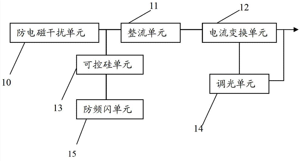
[0012] Such as figure 1 As shown, the dimmable LED driving power supply of the present invention includes an anti-electromagnetic interference unit 10 , a rectification unit 11 , a current conversion unit 12 , a thyristor unit 13 , a dimming unit 14 and an anti-flicker unit 15 . The anti-electromagnetic interference unit 10, the rectification unit 11, and the current conversion unit 12 are connected in sequence, the output of the current conversion unit 12 is fed back to the current conversion unit 12 through the dimming unit 14, and the anti-flicker unit 15 is connected to the rectification unit 11 through the thyristor unit 13. connected to the input.

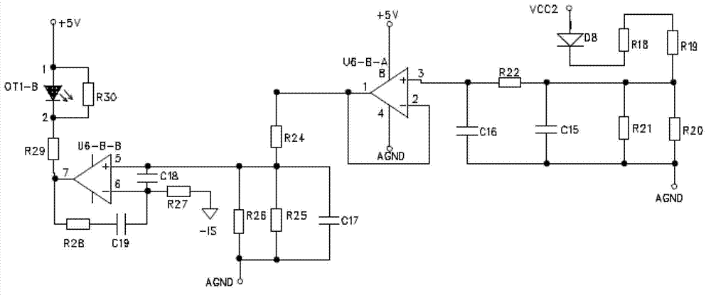
[0013] Such as figure 2 As shown, the dimming unit 14 includes a resistance-capacitance network composed of a diode D8, resistors R18, R19, R20, R21, and capacitors C15 and C16 connected in sequence, a voltage follo...


PUM


Abstract

The invention provides a dimmable light-emitting diode (LED) driving power supply, comprising an electromagnetic-interference resisting unit, a rectifying unit, a current transforming unit, a silicon-controlled unit, a dimming unit and a strobing resisting unit. The strobing resisting unit comprises two diodes, a resistance-capacitance network, a voltage follower, a transistor and a field-effect transistor; the anodes of the two diodes are connected with the silicon-controlled unit, and the cathodes of the two diodes are connected with the drain electrode of the field-effect transistor and are also connected with one input end of the voltage follower through the resistance-capacitance network; the other input end of the voltage follower is connected with the output ends of the diodes; the source electrode of the field-effect transistor is connected with the collector electrode of the triode through the resistance, and the collector of the triode is connected with the ground; signals output by the voltage follower are used for controlling the work state of the triode; and when the conduction angle of the field-effect transistor decreases and is in the wave trough, the triode is fully conducted with the field-effect transistor to maintain the conduction current of the silicon-controlled unit, thereby ensuring the silicon-controlled unit to be in the conduction state and preventing the silicon-controlled unit from being conducted repeatedly to strobe.

Description

technical field [0001] The invention relates to an LED driving power supply, in particular to a dimmable LED driving power supply. Background technique [0002] LED (Light Emitting Diode) has the advantages of low power consumption, long service life, and low cost. It is widely used in lighting, display and other fields, such as LED lighting, LED display screen, LED lighting and so on. [0003] The power of traditional dimmers is relatively large (200W ~ 600W), and the thyristor needs a certain holding current to maintain its conduction. However, in low-power LED driving applications, it is generally impossible to ensure that there is a large enough input current to maintain controllability. Silicon works stably. In this way, multiple conductions may occur, so the voltage and related signals supplied to the LED driver will be unstable. If the dimming signal is not handled properly, the LED will flicker. Contents of the invention [0004] The purpose of the present invent...

Claims


Application Information

Patent Timeline
Patent Type & Authority Patents(China)
IPC IPC(8): H05B37/02
Inventor 黄鹤鸣
Owner SHENZHEN COLLESUN LIGHTING
Why Eureka
Try Eureka