Multidirectional combined type circulating upsetting device and upsetting method

A compound and upsetting technology, applied in the field of plastic forming, can solve the problems of small deformation, high processing temperature, and material side cracking, and achieve the effects of large deformation, improved ultra-fine degree, and sufficient flow

Active Publication Date: 2011-04-27
上海治实合金科技有限公司
View PDF6 Cites 13 Cited by
  • Summary
  • Abstract
  • Description
  • Claims
  • Application Information

AI Technical Summary

Problems solved by technology

However, when using this method to prepare materials that are difficult to deform, it is usually necessary to select a higher processing temperature, and high temperature processing will have a negative impact on the grain refinement of the material
If you choose a lower temperature, since the side of the material is not limited by the reaction force of the mold, it is easy to form a side arc during processing, and it is difficult to return to the original shape after each step of processing, which is not convenient for subsequent processing. In severe cases, the side of the material may even occur cracked, resulting in processing failure
In addition, there is no corner shear deformation similar to equal channel angular extrusion, and the amount of deformation per pass of multi-directional forging is small, and the prepared ultra-fine-grained materials still have certain deficiencies in the uniformity and refinement of the structure.

Method used


Image

  • Multidirectional combined type circulating upsetting device and upsetting method
  • Multidirectional combined type circulating upsetting device and upsetting method
  • Multidirectional combined type circulating upsetting device and upsetting method

Examples


Embodiment Construction

[0027] The embodiments of the present invention are described in detail below. This embodiment is implemented on the premise of the technical solution of the present invention, and detailed implementation methods and specific operating procedures are provided, but the protection scope of the present invention is not limited to the following implementation example.

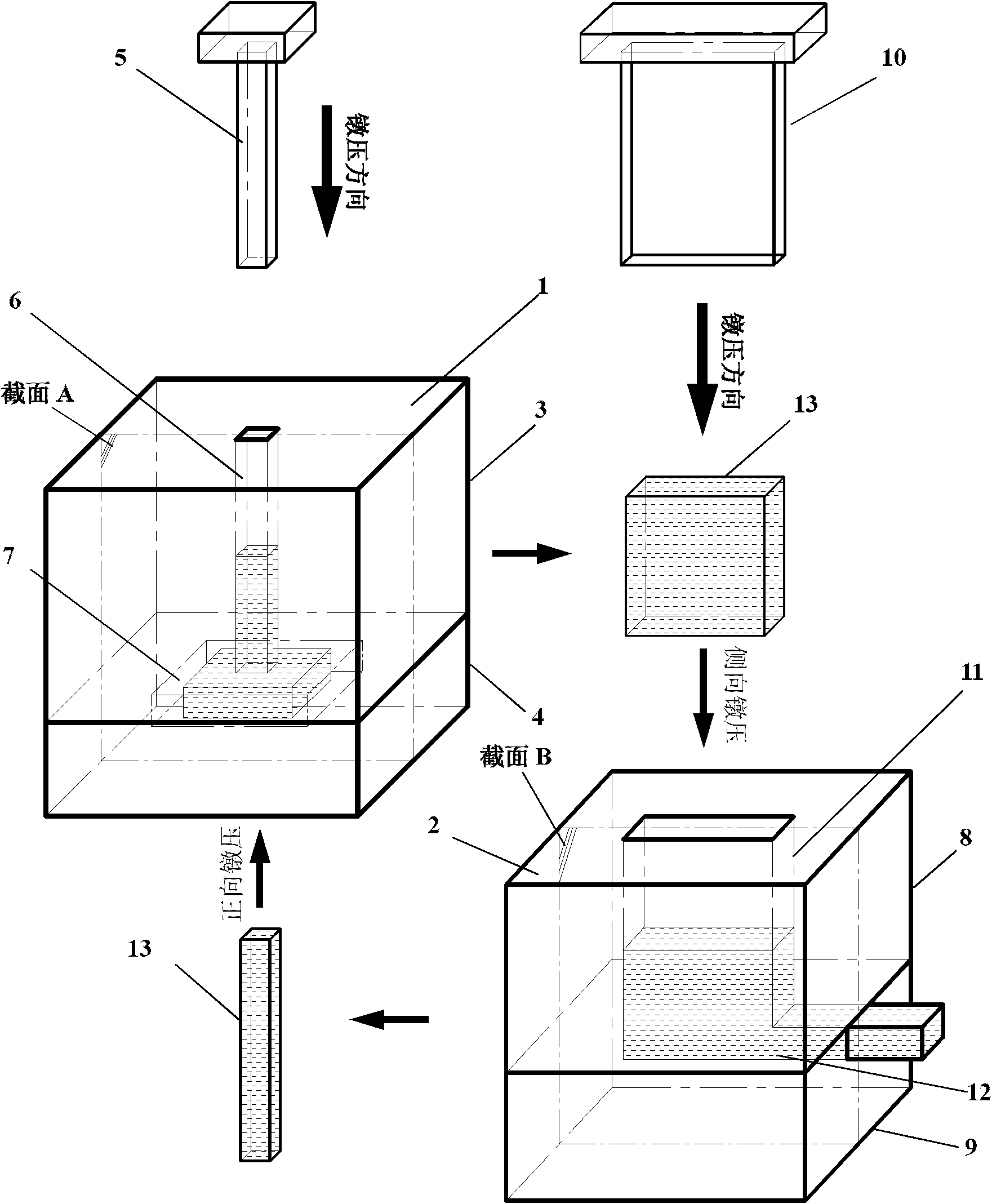
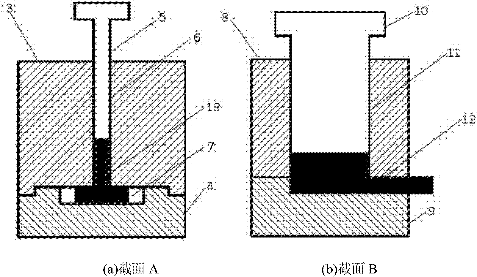
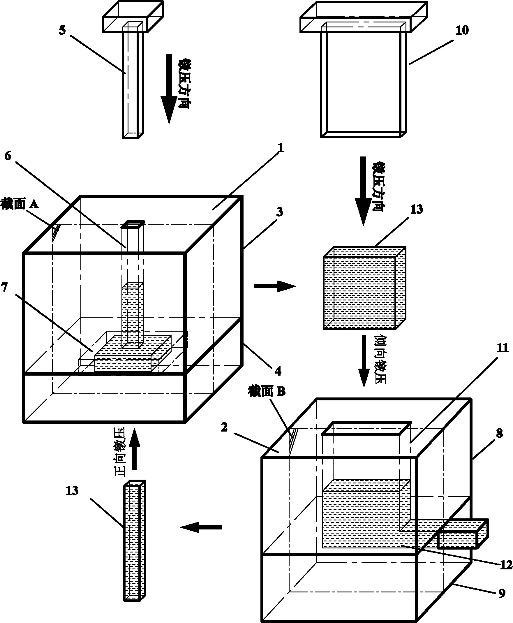
[0028] Such as figure 1 As shown, the upsetting device involved in the following embodiments includes: a forward upsetting device 1 and a side upsetting device 2, wherein:

[0029] The positive upsetting device 1 includes: a positive upper die 3, a positive lower die 4 and a forward punch 5, wherein: the positive upper die 3 and the positive lower die 4 arranged up and down are in contact, and the cross section of the forward punch 5 The size matches the section of the positive model cavity 6;

[0030] The central axis of the positive mold 3 is provided with a positive mold cavity 6 from top to bottom, and the po...


PUM

PropertyMeasurementUnit
sizeaaaaaaaaaa
sizeaaaaaaaaaa

Abstract

The invention relates to a multidirectional combined type circulating upsetting device and an upsetting method thereof, and belongs to the technical field of plastic forming. The upsetting device comprises a forward upsetting device and a lateral upsetting device. The method comprises the following steps of: in the forward upsetting process, prearranging bar blanks of which the cross sections are square in a forward upper die cavity of the forward upsetting device, so that the blanks are subjected to compressive plastic deformation downwards to fill in a forward lower die cavity finally; opening the forward upsetting device, taking the blanks out and putting the blanks in a lateral upper die cavity of the lateral upsetting device, with the side face facing downward, so that test samples are subjected to lateral upsetting deformation towards an lateral opening in a lateral lower die, and stopping pressing until a lateral punch presses to a parting surface of the lateral upsetting device; and repeating the steps for multiple times to perform multidirectional combined type upsetting circularly. By the upsetting device, superfine crystal blocks with uniform tissue can be prepared, so the upsetting device is used for preparing various superfine crystal materials such as pure metals, alloys, intermetallic compounds, composite materials, high polymer materials, semiconductor materials and the like.

Description

technical field [0001] The invention relates to a method in the technical field of plastic forming, in particular to a multi-directional composite cycle upsetting device and an upsetting method. Background technique [0002] The large plastic deformation technology, referred to as SPD, has a remarkable ability to refine grains, and can refine the grain structure of materials to submicron or even nanometer levels. Promising approach. However, the uniformity of the bulk material structure and the continuity and controllability of the process have always been the main problems of the large plastic deformation technology. [0003] After searching the literature of the prior art, it was found that the Chinese patent number ZL200710045628.3, the name of the invention: an upsetting mold for preparing large ultra-fine-grained materials, the patent uses a parting mold composed of upper and lower cavities. The punch with the same cross-section of the cavity exerts pressure on the ma...

Claims


Application Information

Patent Timeline
Patent Type & Authority Applications(China)
IPC IPC(8): B21C23/02
Inventor 周浩王渠东郭炜
Owner 上海治实合金科技有限公司
Why Eureka
Try Eureka