
Sleeve valve with adjustable longitudinal flow

A vertical flow and adjustable technology, applied in the field of valves, can solve the problems of not meeting the vertical fluid flow direction, large leakage, inconvenient control of upper and lower water levels, etc.

Inactive Publication Date: 2011-04-27
LANSHEN GRP CORP LTD
View PDF3 Cites 4 Cited by
  • Summary
  • Abstract
  • Description
  • Claims
  • Application Information

AI Technical Summary

Problems solved by technology

[0004] 1. Due to the constraints of its own structure, it can only be used to control the front and rear water levels, and the requirements for installation conditions are more formal;
[0005] 2. Large leakage, generally 1.25L / m min;
[0006] 3. It is not convenient to control the upper and lower water levels
At this time, it is necessary to use a new device to meet the adjustment of the water level and water volume between the upper and lower pools, and the existing valves are only suitable for the occasions where the fluid flow direction is horizontal, and cannot meet the requirements of the longitudinal fluid flow direction.

Method used


Image

  • Sleeve valve with adjustable longitudinal flow
  • Sleeve valve with adjustable longitudinal flow
  • Sleeve valve with adjustable longitudinal flow

Examples


Embodiment Construction

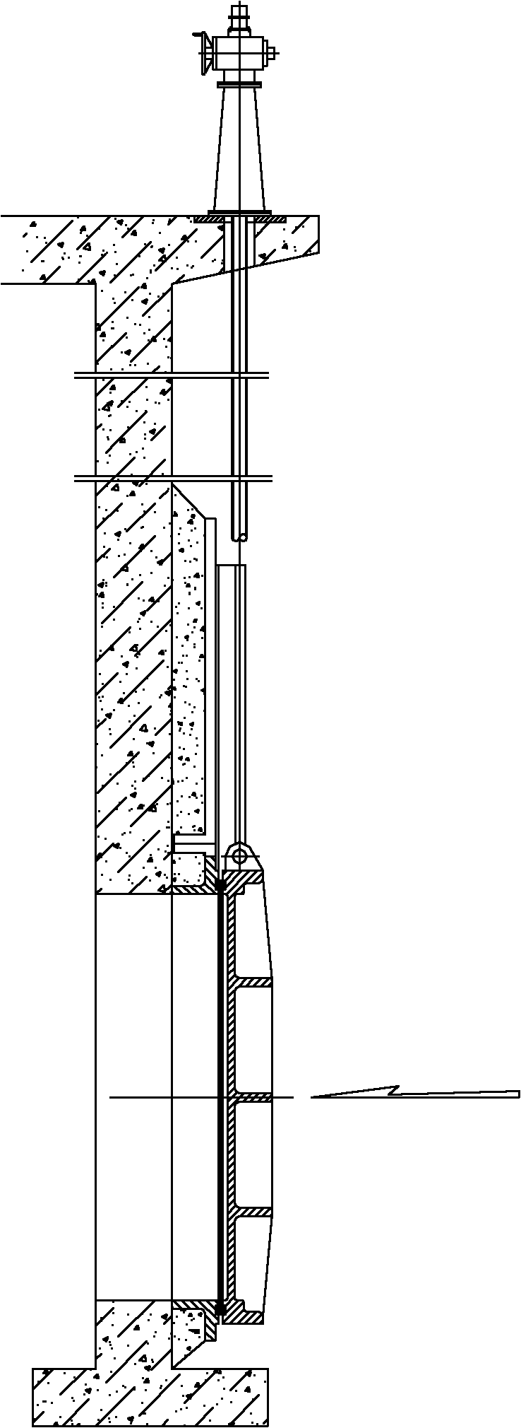
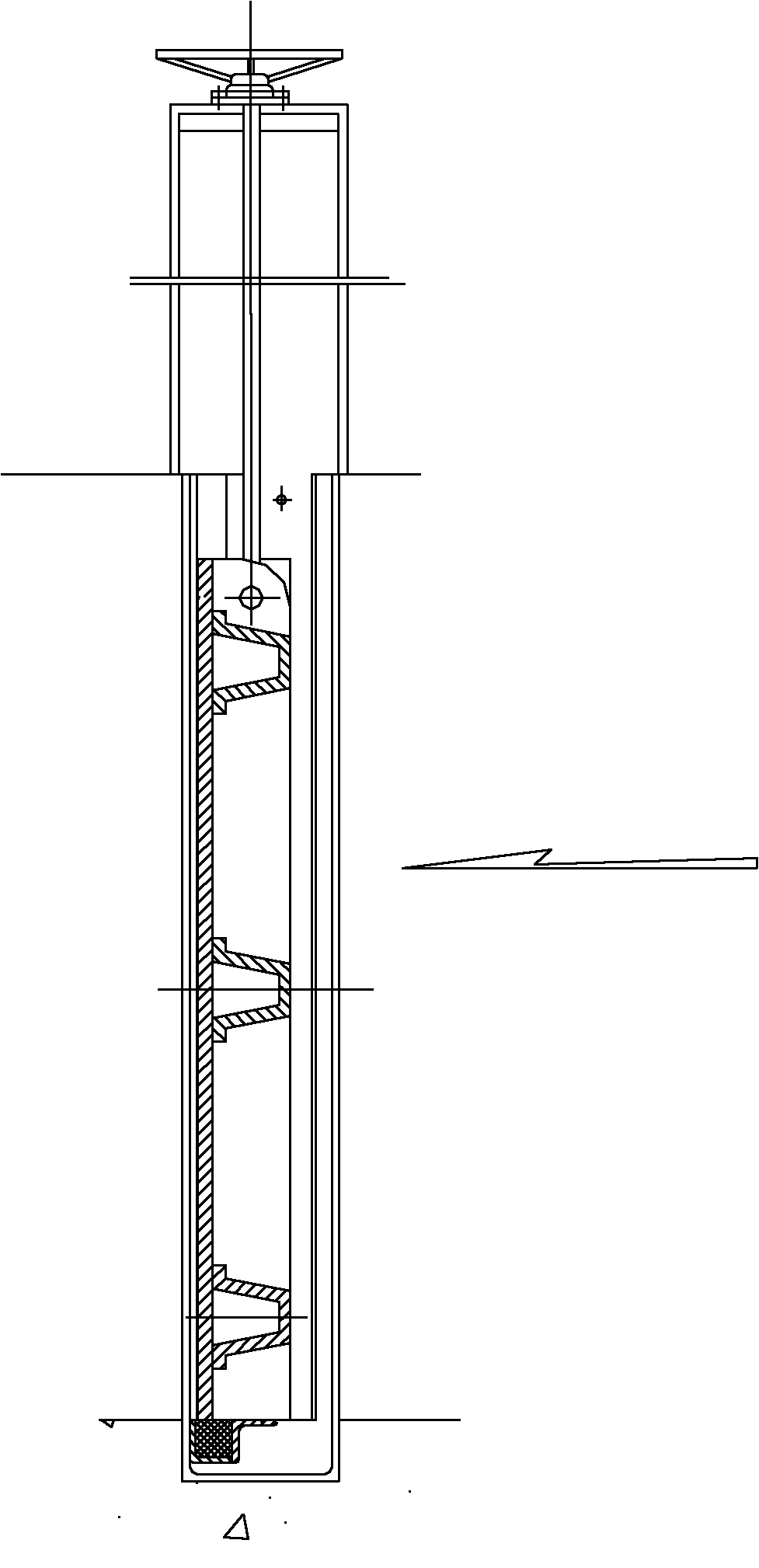
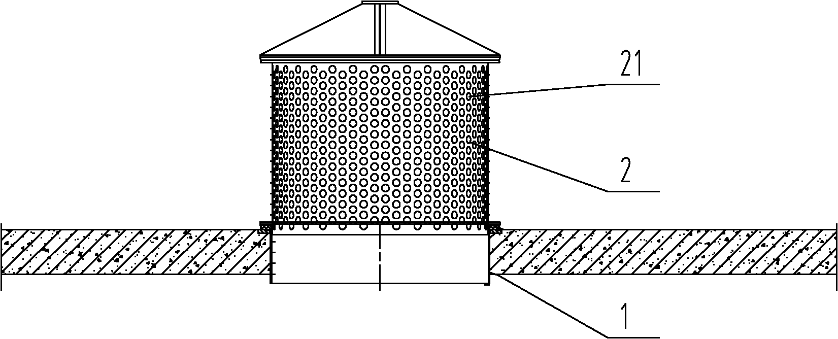
[0018] A sleeve valve with adjustable longitudinal flow, comprising: a valve sleeve 1, a piston cylinder 2 is arranged in the valve sleeve 1, and a sliding fit is formed between the piston cylinder 2 and the valve sleeve 1, and a guide is provided on the piston cylinder 2. Orifice 21. In this embodiment, considering the requirements of flow control and total flow (ie the maximum flow), the sum of the areas of all the diversion holes 21 on the piston barrel 2 is equal to the inner area of ​​the valve sleeve 1 .

[0019] During specific use, the present invention is installed on the platform between the upper and lower pools of the stacked structure, and the piston cylinder 2 is connected to the lifting device 3, and the lifting device 3 is used to drive the piston cylinder 2 to move up and down. The lifting device 3 Including frame 32, frame 32 is provided with hoist 31, is screwed with drive screw mandrel 33 at hoist 31, hoist 31 can be purchased from the market, and drive scr...


PUM


Abstract

The invention discloses a sleeve valve with an adjustable longitudinal flow, which comprises a valve bush, wherein a piston cylinder is arranged in the valve bush, sliding matching is formed between the piston cylinder and the valve bush, and guide holes are arranged on the piston cylinder. The sleeve valve is arranged between an upper pool and a lower pool, in particular, a hole is drilled on a platform between the upper pool and the lower pool, the valve bush is fixed on the hole in a manner of an expansion bolt or embedded steel plate, the upper end face of the valve bush is embedded with a flat rubber ring to be used as an end face seal, and the piston cylinder is arranged on the valve bush, therefore, because the valve body is structurally characterized by being closed and opened by a sleeve vertical motion, when the piston cylinder moves upwards, the guide holes of the piston cylinder play a role of guiding, with the increase of the lifting amount, the total guide area is continuously increased until the piston cylinder passes through the complete stroke, and the valve is equally completely opened. When the piston cylinder moves downwards, the quantity of the guide holes on the side surface is continuously reduced until the flat rubber end face is in complete contact with a fixed cylinder to play a role of sealing, and the valve is completely closed.

Description

technical field [0001] The invention relates to a valve, in particular to a sleeve valve with adjustable longitudinal flow used in water conservancy and water treatment projects. [0002] Background technique [0003] Existing water level and water volume adjustment equipment mainly include cast iron gates inlaid with copper, channel gates, stacking beam gates, rotary weir gates and various flat valves (such as butterfly valves, etc.), which are realized by manual hoist or electric hoist. Linear and rotary motion of the gate valve to achieve the purpose of adjusting the water level. The limitations and disadvantages of this type of gate valve are: [0004] 1. Due to the constraints of its own structure, it can only be used to control the front and rear water levels, and the requirements for installation conditions are more formal; [0005] 2. Large leakage, generally 1.25L / m min; [0006] 3. It is not convenient to control the upper and lower water levels. Especially in...

Claims


Application Information

Patent Timeline
IPC IPC(8): E02B8/04E02B5/08
Inventor 陈晓军陈斌董绵杰李善庭杨加林许荣军朱永
Owner LANSHEN GRP CORP LTD
Learn More