Split solar power system

A solar and split technology, applied in the field of circulation pipelines, can solve the problems of difficulty in promotion and high cost of split solar systems

Inactive Publication Date: 2011-04-27
SHANDONG LINUO PARADIGMA
View PDF6 Cites 0 Cited by
  • Summary
  • Abstract
  • Description
  • Claims
  • Application Information

AI Technical Summary

Problems solved by technology

[0007] For this reason, the present invention provides a split solar system with a compact structure, low cost and low maintenance cost in order to solve the defect that the current split solar system is so expensive that it is difficult to popularize.

Method used


Image

  • Split solar power system
  • Split solar power system
  • Split solar power system

Examples


Embodiment Construction

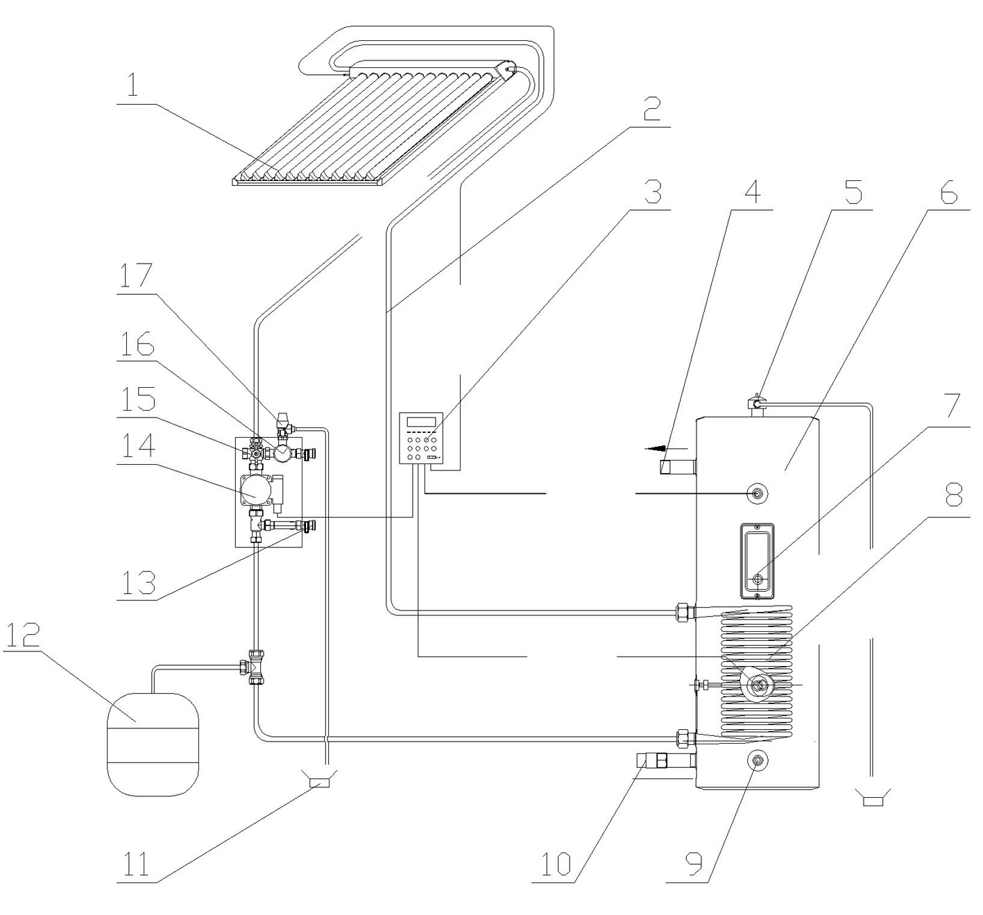
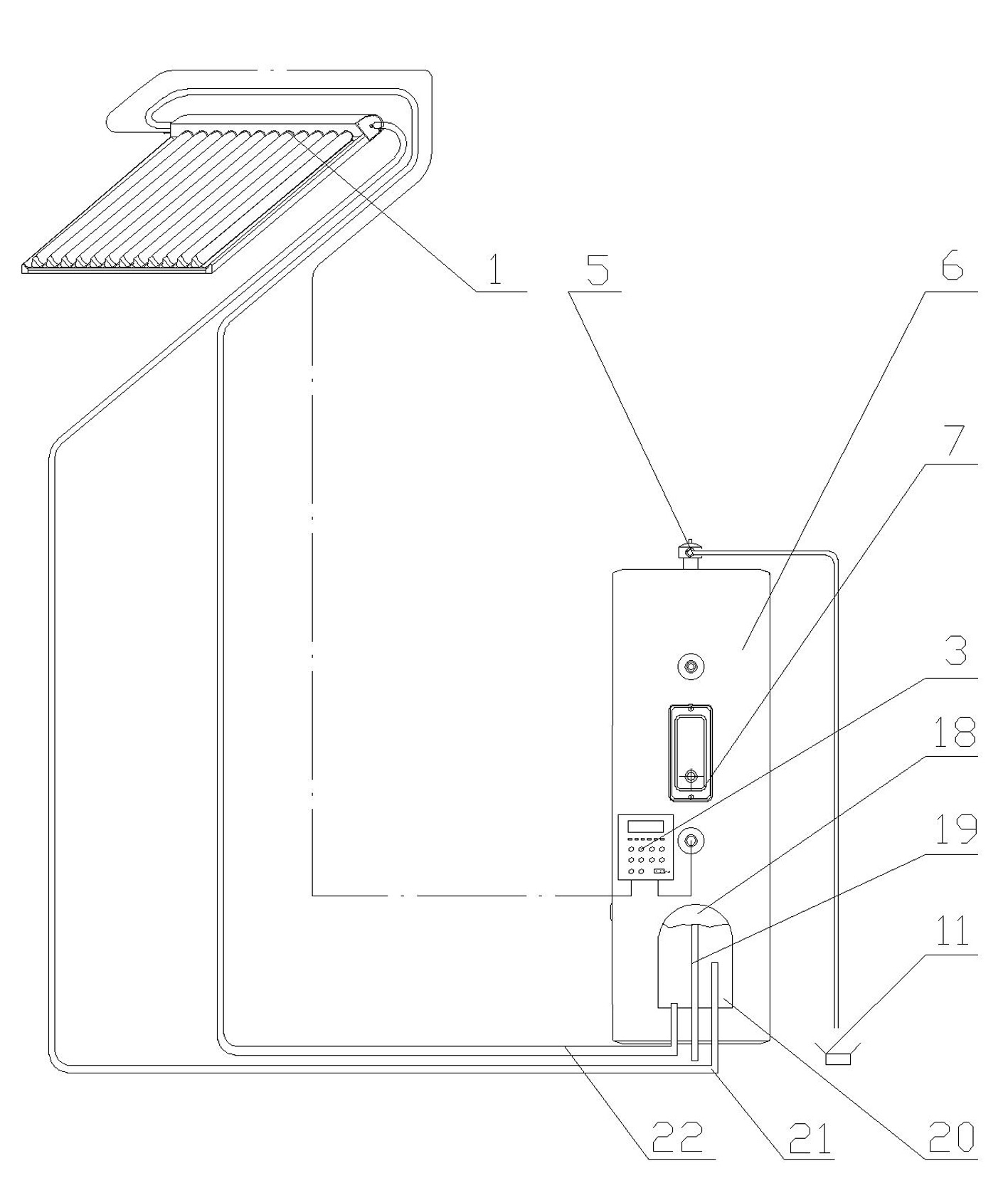
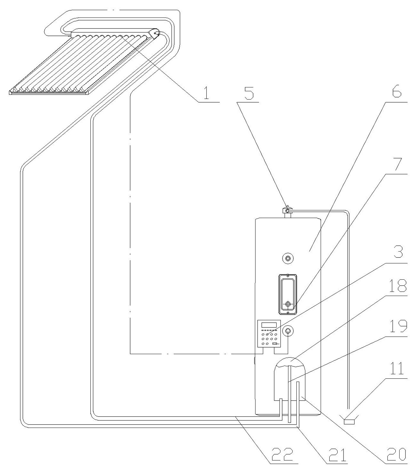
[0027] Refer to attached figure 2 , which shows a split solar system, its basic scheme is that it includes a heat collector 1 and a water tank 6 with built-in heat exchange components, and a circulation pipeline 2 connecting the heat collector and the heat exchange components, The heat exchange component is a small gallbladder 20 with fins, which is also vertically provided with an exhaust pipe 19 with a safety valve extending out of the water tank; wherein the small gallbladder reserves an expansion space 18.

[0028] On the basis of the above basic scheme, those skilled in the art can choose or combine the following technical means:

[0029] As for the collector, it should be a pressurized collector, which is determined by the properties of the split solar system. In this scheme, the heat collector can be placed higher than the water tank to meet the basic requirements of thermosiphon, and it can also be equipped with a circulation pump.

[0030] The nominal volume of th...


PUM


Abstract

The invention discloses a split solar power system, which comprises a heat collector, a water tank in which a heat exchange part is arranged, and a circulation loop connected with the heat collector and the heat exchange part, wherein the heat exchange part is a small liner with a fin; the small liner is also provided with an exhaust pipe which extends out of the water tank and is provided with a safety valve in the vertical direction; and expansion space is reserved in the small liner. The split solar power system is compact in structure, low in cost and post maintenance cost.

Description

technical field [0001] The invention relates to a split solar energy system, which comprises a heat collector, a water tank with built-in heat exchange components, and a circulation pipeline connecting the heat collector and the heat exchange components. Background technique [0002] At present, water heaters used at home and abroad mainly include electric water heaters, gas water heaters, solar water heaters, heat pump water heaters, etc. Solar water heaters and heat pump water heaters are emerging new energy water heaters in recent years, which have great promotion value. [0003] There are many forms of solar water heaters in China: according to the type of system, there are mainly compact solar systems (ordinary solar systems), separated solar systems (vacuum tubes and water tanks are separated), and stuffy solar systems; system, all-glass vacuum tube solar system, glass-metal vacuum tube solar system, sun-dried solar system; according to the heat transfer type, it can b...

Claims


Application Information

Patent Timeline
Patent Type & Authority Applications(China)
IPC IPC(8): F24J2/30F24J2/46F24J2/00F24S10/30
CPCY02E10/44
Inventor 马迎昌丰中玉王城路李方军
Owner SHANDONG LINUO PARADIGMA
Why Eureka
Try Eureka