
Preparation method of dye-sensitized solar cell provided with light reflecting layer

A technology of solar cells and light reflection layers, applied in the field of dye-sensitized solar cells, can solve problems such as light energy loss, achieve the effects of low cost, improve light energy utilization rate, and suppress light energy loss

Inactive Publication Date: 2012-03-28
上海联孚新能源科技集团有限公司
View PDF0 Cites 0 Cited by
  • Summary
  • Abstract
  • Description
  • Claims
  • Application Information

AI Technical Summary

Problems solved by technology

The high transparency of the dye-sensitized solar cell can make the dye contact with more photons and release more electrons, but the light will directly pass through the platinum counter electrode after being incident on the working electrode, causing serious light energy loss and inhibiting The further growth of photocurrent and the improvement of light energy conversion rate

Method used


Image

  • Preparation method of dye-sensitized solar cell provided with light reflecting layer
  • Preparation method of dye-sensitized solar cell provided with light reflecting layer
  • Preparation method of dye-sensitized solar cell provided with light reflecting layer

Examples


Embodiment 1

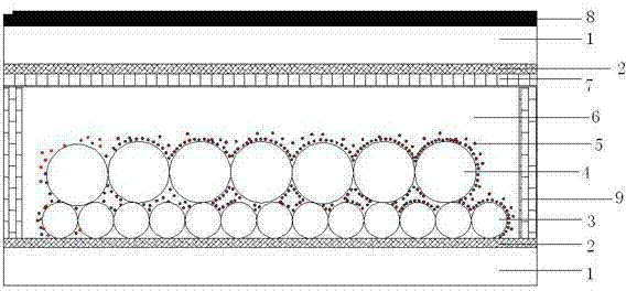
[0027] (a) Cleaning: Clean the conductive glass; use deionized water, absolute ethanol, and acetone to clean in an ultrasonic cleaner for 10 minutes, and dry in an oven; prepare 40mM TiCl 4 Solution, soak conductive glass (FTO), and dry at 70°C for 30 minutes;

[0028] Sinter the treated FTO, use an atmosphere furnace to keep warm at 325°C for 5-10 minutes, then raise the temperature to 375°C for 5-10 minutes, then raise the temperature to 450°C and keep it for 10-15 minutes, and finally raise the temperature to 500°C And keep warm for 10-15 minutes;

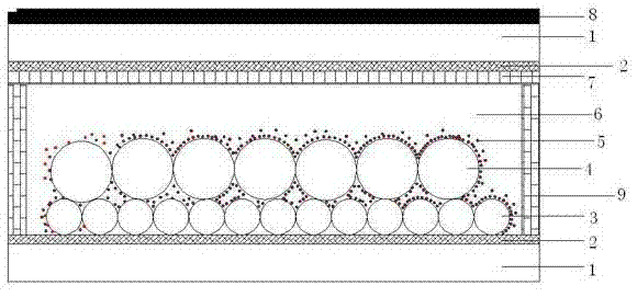
[0029] (b) Preparation of TiO 2 Nano-transparent layer: the prepared 25nm TiO 2 The slurry is coated on the surface of FTO to form TiO 2 The nano-transparent layer 3 is controlled to have a thickness of 14-16 μm through homogenization and drying processes;

[0030] (c) Preparation of TiO 2 Light scattering layer: on TiO 2 A layer of 400nmTiO is silk-screened on top of the nano-transparent layer 2 light scattering layer 4;...

Embodiment 2

[0037] This embodiment is completely the same as Embodiment 1 in steps a to d, the difference is that:

[0038] (e) Adhesive total reflection mirror, electrode butt joint packaging: the total reflection mirror is bonded to the surface of the counter electrode as a light reflection layer in an oven at 120 ° C; the counter electrode bonded with the total reflection mirror is docked with the photoanode , using sarin film for encapsulation;

[0039] (f): Injection electrolyte: In vacuum environment, inject electrolyte 6, electrolyte 6 is I -1 / I 3 -1 redox pair;

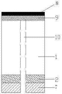
[0040] (g) Sealing of the electrolyte injection port: The electrolyte injection port 10 was sealed with a sarin film to manufacture a solar cell.

[0041] The dye-sensitized solar cells prepared in the two examples can completely reflect the light passing through the counter electrode of the cell, effectively suppress the loss of light energy, improve the utilization rate of light energy, and further increase the lig...


PUM


Abstract

The invention discloses a preparation method of a dye-sensitized solar cell provided with a light reflecting layer, which comprises the following process steps: (a) cleaning; (b) preparing a TiO2 nano-transparent layer; (c) preparing a TiO2 light scattering layer; (d) forming a light anode; (e) bonding the reflecting layer; (f) butting and packaging electrodes; (g) injecting electrolyte; and (h) sealing an electrolyte injection opening to obtain the solar cell. The dye-sensitized solar cell prepared by the invention can fully reflect the light which permeates through the counter electrodes of the cell, so that the loss of the light energy is effectively inhibited, and the utilization rate of the light energy is improved, thereby improving the conversion rate of the light energy of the cell. Moreover, the preparation method provided by the invention is simple in operation, has low cost and can not influence the whole preparation processes of the solar cell.

Description

technical field [0001] The invention belongs to the field of dye-sensitized solar cells, and in particular relates to a method for preparing a dye-sensitized solar cell with a light reflection layer on a counter electrode. Background technique [0002] Since 1991, Professor Michael of the Swiss Federal Institute of Technology in Lausanne After Nature magazine reported the preparation method of the third-generation solar cell-dye-sensitized solar cell (DSSC) and its light energy conversion rate of 7.1-7.9%, it attracted great attention from relevant scholars at home and abroad. Compared with other solar cells, DSSC has the advantages of simple preparation process, low manufacturing price, non-toxic and non-polluting preparation materials, etc. Its light energy conversion rate is also increasing year by year. According to reports, at present Michael The light energy conversion rate of DSSC prepared by the experimental group has exceeded 12%, and there is still a lot of roo...

Claims


Application Information

Patent Timeline
Patent Type & Authority Patents(China)
IPC IPC(8): H01G9/048H01G9/20H01M14/00H01L51/48
CPCY02E10/542Y02E10/549
Inventor 罗军苏青峰赖建明张根发吴明明王长君李帅
Owner 上海联孚新能源科技集团有限公司
Learn More