New method for miniaturization design of planar helical antenna

A design method, the technology of planar spiral, applied in the direction of antenna, antenna grounding device, radiation element structure, etc., to achieve the effect of size reduction

Inactive Publication Date: 2011-04-27
BEIJING UNIV OF POSTS & TELECOMM
View PDF2 Cites 5 Cited by
  • Summary
  • Abstract
  • Description
  • Claims
  • Application Information

AI Technical Summary

Problems solved by technology

But there are only few studies on the miniaturization of planar helical antennas

Method used


Image

  • New method for miniaturization design of planar helical antenna
  • New method for miniaturization design of planar helical antenna
  • New method for miniaturization design of planar helical antenna

Examples


Embodiment Construction

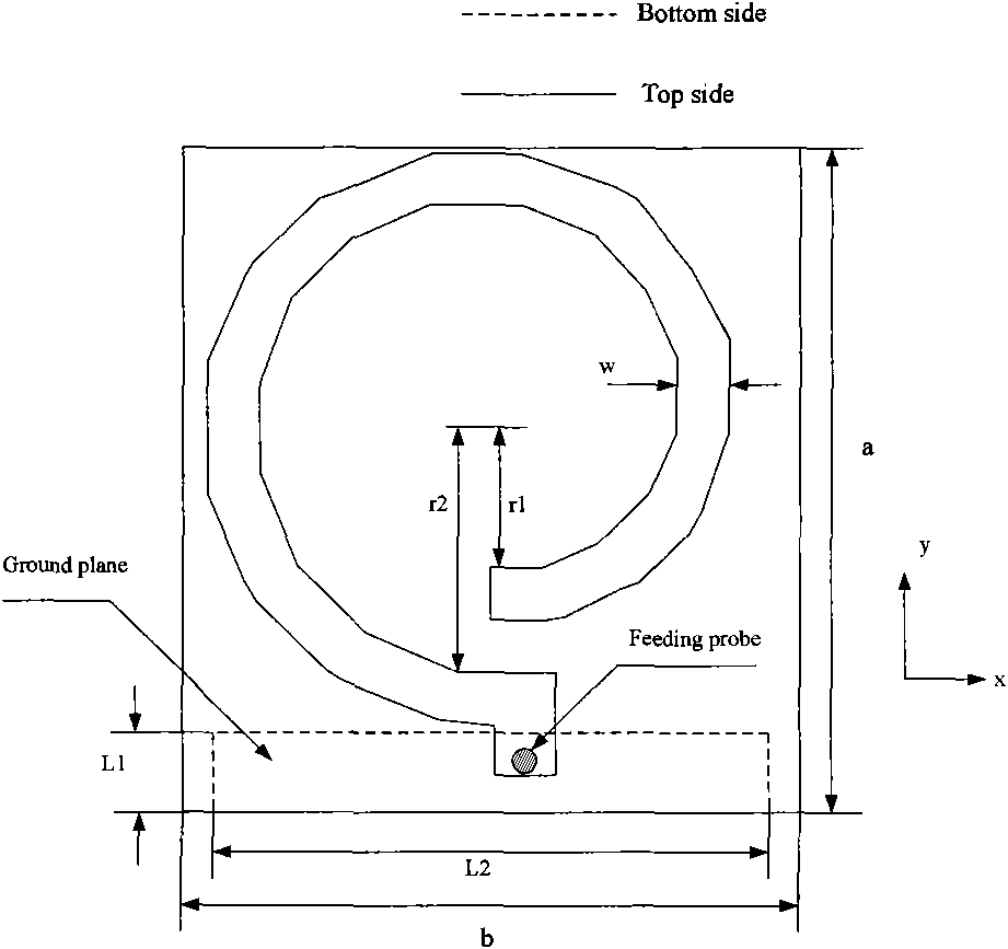
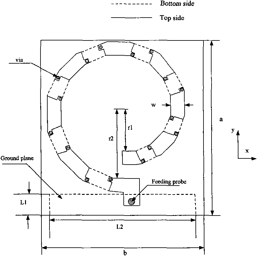
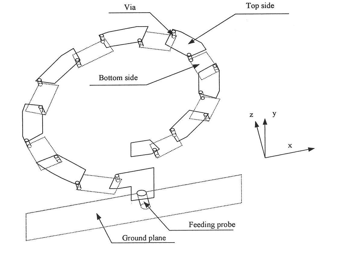
[0017] The antenna miniaturization design method disclosed in the present invention divides the conventional spiral patch into several small segments, and places half of the small segments on the upper layer of the dielectric board, and the other half on the lower layer of the dielectric board. Slices are connected. Thus, the number of metal probes determines the degree of antenna size reduction. By increasing the number of metal probes, the resonant frequency of the antenna is reduced, and the size of the antenna is reduced.

[0018] The measured results of planar helical antennas with four new structures and conventional structures are given below. Structural parameters: r1=15mm, r2=25mm, w=5mm, L1=7mm, L2=86mm, a=70mm, b=92mm. The radius of each probe is 0.3mm. Both the new structure and the conventional structure use a dielectric plate with a thickness of 2mm and a dielectric constant of 2.65, and a coaxial probe with a radius of 0.5mm is used for feeding. It can be see...


PUM


Abstract

The invention discloses a new method for effectively reducing the size of a planar helical antenna, in particular to the design of an improved planar helical antenna. A general helical antenna patch is cut into a plurality of small segments, small metal segments are alternately arranged on an upper layer and a lower layer of a medium board and the patch segments of the upper layer and the lower layer are made to communicate through metal probes. By increasing the number of the metal probes, the antenna has reduced resonance frequency points and reduced size. The simple single-ring spiral patch antenna and corresponding four novel antenna structures designed by adopting the method are manufactured. Shown by simulation and the analysis of experimental results, the more segments are cut, the more probes are adopted, the greater the reduction degree of the antenna size is, and the size of the antenna is reduced by more than 80 percent. The antenna of the type has the advantages of small size, light weight and easy processing, is a novel low-cost miniaturized planar antenna and has wide application prospects.

Description

technical field [0001] The invention relates to the application of a planar helical antenna, in particular to a novel method for reducing the size of the planar helical antenna. Background technique [0002] Recently, research on antenna miniaturization technology is attracting more and more attention, and researchers have proposed many different new methods to reduce the size of antennas. Digging square or cross-shaped slots on the patch or floor of the microstrip antenna can effectively reduce the size of the antenna. A microstrip antenna with a square slot can be reduced in size by about 17%. If a cross-shaped slot is used, the corresponding size reduction is about 23%. If cross slots are dug on the floor of the microstrip antenna, the size of the antenna can be reduced by 55%. All of the above techniques are applied to simple microstrip antennas. Recently, the application of planar helical antennas in communication systems has attracted increasing attention. The pla...

Claims


Application Information

Patent Timeline
IPC IPC(8): H01Q1/38H01Q1/48H01Q13/08
Inventor 李书芳邓力洪卫军尹斯星左中梁
Owner BEIJING UNIV OF POSTS & TELECOMM
Why Eureka
Try Eureka