Programmable digital frequency multiplier

A frequency multiplier and frequency multiplication technology, applied in the direction of power oscillators, electrical components, etc., can solve the problems of increased volume, low frequency and phase tracking accuracy, complex frequency control algorithm, etc., to ensure zero error output and anti-interference The effect of ability improvement

Inactive Publication Date: 2011-04-27
SUZHOU R&D CENT OF NO 214 RES INST OF CHINA NORTH IND GRP
View PDF2 Cites 18 Cited by
  • Summary
  • Abstract
  • Description
  • Claims
  • Application Information

AI Technical Summary

Problems solved by technology

In addition, due to the complexity of the frequency control algorithm, CPLD / FPGA or single-chip microcomputer must be used for calculation and control
[0005] Therefore, in the implementation of the above frequency multiplier, the frequency multiplier using the phase-locked loop has the disadvantage of slow tracking speed, and its performance in the low frequency band is difficult to meet the actual requirements. Slow, especially for ultra-low frequency signals around 2HZ, the steady-state locking time is about 12S, and the tracking accuracy of frequency and phase is relatively low
In addition, the output frequency of the VCO in the phase-locked frequency multiplier can only deviate from the center frequency within a certain range
Therefore, in an actual circuit, it is impossible for a phase-locked loop to cover the entire frequency range required by the design, so multiple frequency multiplier circuits are required, making the circuit very complicated
Using direct digital frequency synthesizer (DDS) to design the frequency multiplier, because CPLD / FPGA or single-chip microcomputer must be used for calculation and control, the circuit structure is complicated and the volume is increased. In addition, because the crystal oscillator above 100MHz must be used, It is easy to cause interference to the circuit itself or interfere with other circuits

Method used


Image

  • Programmable digital frequency multiplier
  • Programmable digital frequency multiplier
  • Programmable digital frequency multiplier

Examples


Embodiment Construction

[0026] Below in conjunction with accompanying drawing, preferred specific embodiment of the present invention is described:

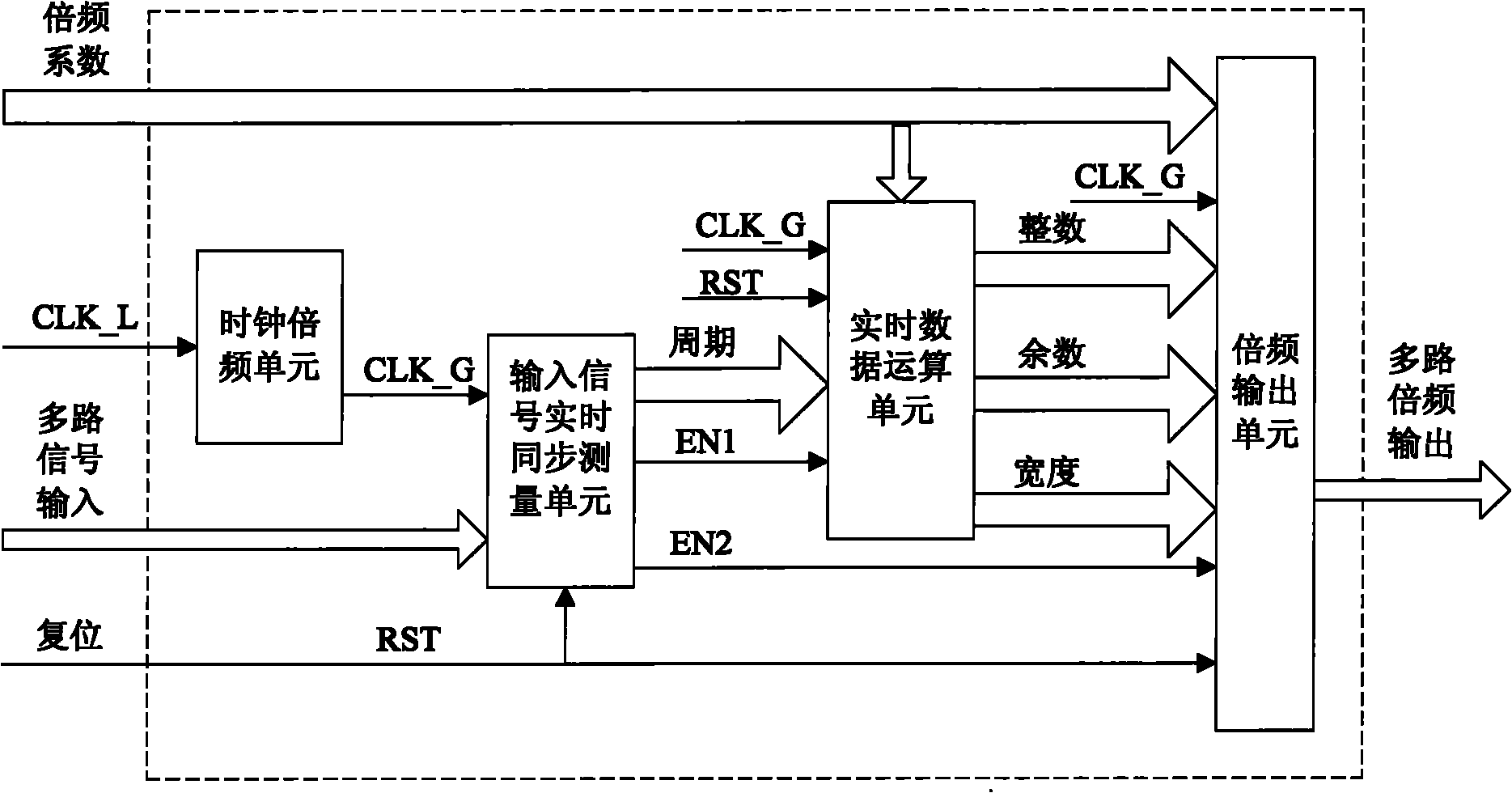
[0027] Such as figure 1 The frequency multiplier shown is mainly composed of clock frequency multiplication unit, input signal real-time synchronous measurement unit, real-time data calculation unit, frequency multiplication output unit and other module units. Each functional unit is realized by digital circuit, which can be packaged in a On the chip, as shown by the dotted line in the figure, some input and output pins are arranged on the periphery of the chip. In the present invention, the input pins include the input of the frequency multiplication coefficient, the input of the system low-frequency clock CLK_L, the input of the input signal to be multiplied and the reset Signals, etc., the output pins only show the multiplier signal output in the attached figure. The following will introduce each functional unit in detail:

[0028] The clock frequen...


PUM


Abstract

The invention relates to a programmable digital frequency multiplier comprising a clock frequency multiplier unit, an input signal real-time synchronous measuring unit, a real-time data operation unit and a frequency multiplier output unit. The clock frequency multiplier unit is used for receiving and converting a clock signal of an external low-frequency system into a high-frequency sampling clock signal needed by other units in the frequency multiplier, the input signal real-time synchronous measuring unit is connected with the high-frequency sampling clock signal output end of the clock frequency multiplier unit and used for receiving an input signal to be multiplied in frequency and carrying out the synchronous periodic counting to the input signal by utilizing the high-frequency sampling clock signal so as to output a period counting value, the real-time data operation unit receives a to-be-multiplied coefficient and carries out division operation to the period counting value andthe frequency multiplication coefficient by utilizing the high-frequency sampling clock signal, and the frequency multiplier output unit receives the to-be-multiplied coefficient, selects a suitable pulse period according to the relation between an integer and a remainder and outputs N multiplied pulse signals with zero error. The invention greatly improves the whole anti-interference capability of the circuit by external inputting low-frequency clock and can be particularly applied to an I/F (Interface) conversion post-stage circuit.

Description

technical field [0001] The invention relates to a frequency multiplier, in particular to a digital frequency multiplier which can work at a lower frequency. Background technique [0002] A frequency multiplier is a circuit whose output signal frequency is an integer multiple of the input signal frequency. The function of the frequency multiplier is to insert a certain number of pulses at equal intervals between two input pulses, so that the output frequency of the signal passing through the frequency multiplier is equal to the multiple of the input frequency. The frequency multiplier is widely used, such as the frequency multiplier used in the transmitter can improve the frequency stability, the frequency multiplier used in the FM equipment can increase the frequency offset, and the frequency multiplier in the phase keying communication machine is an important component of the carrier recovery circuit Unit, using a frequency multiplier in the I / F conversion circuit to make ...

Claims


Application Information

Patent Timeline
Patent Type & Authority Applications(China)
IPC IPC(8): H03B19/14
Inventor 张宪起杨侃王丽丽鲁争艳李金宝李贵娇董冀
Owner SUZHOU R&D CENT OF NO 214 RES INST OF CHINA NORTH IND GRP
Why Eureka
Try Eureka