
Data transmission method and equipment

A transmission method and data technology, applied in the field of communication, can solve the problems of low transmission rate, affecting the transmission rate and transmission mode of the SRIO controller, complex buffer management, etc., and achieve the effect of increasing the transmission rate

Inactive Publication Date: 2011-04-27
DATANG MOBILE COMM EQUIP CO LTD
View PDF2 Cites 34 Cited by
  • Summary
  • Abstract
  • Description
  • Claims
  • Application Information

AI Technical Summary

Problems solved by technology

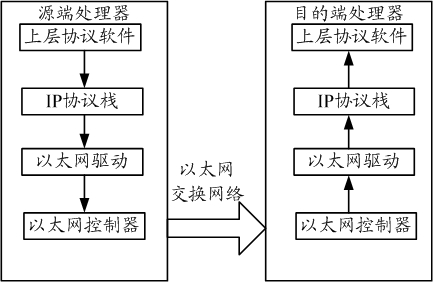
[0010] In the original Ethernet network, the use of IP protocol and Ethernet frame transmission and reception can complete the transmission of large amounts of data between multiple processors, but it has at least the following problems: (1) The transmission rate is low, and the theoretical transmission rate of the Ethernet controller is only 1Gbit / s, it is difficult to meet the needs of high-speed embedded system interconnection; (2) Ethernet transmission is unreliable, when the network is congested, the switching device will choose to discard part of the Ethernet frame data, resulting in data loss; (3) There is a conflict between the Ethernet controller provided by some chip manufacturers and the SRIO (Serial Rapid IO) controller when sharing hardware resources, which affects the transmission rate and transmission mode of the SRIO controller
Among them, the Rapid IO protocol mainly has two types of transactions, IO mode and MSG (message, message) mode; the IO mode has no limit on the transmission size, but requires the sender to understand the physical memory allocation of the peer, and the maintenance of the send and receive buffers The above two parties must strictly agree that when the number of processors in the network is large and the amount of interaction between them is large, the buffer management is complicated and wasteful, and the flexibility is poor; in MSG mode, the sender does not need to know the peer's The actual physical memory, the receiving end stores the data in the locally planned buffer according to the mailbox and letter number and other information. The maintenance of the sending and receiving buffer is relatively simple, but the transmission size cannot exceed 4K, and it can only be used for small-size data transmission
Therefore, in a large multi-processor mixed network, the above two modes have great limitations

Method used


Image

  • Data transmission method and equipment
  • Data transmission method and equipment
  • Data transmission method and equipment

Examples


Embodiment 1

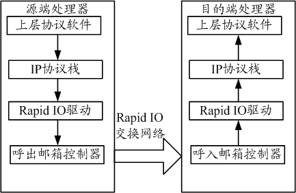
[0037] Embodiment 1 of the present invention provides a data transmission method, which is combined below figure 2 The shown IP protocol stack-based Rapid IO network data transmission process describes the method in detail. exist figure 2Among them, it includes the source-end processor (the processor at the sending end) and the destination-end processor (the processor at the receiving end). The source-end processor and the destination-end processor communicate through the Rapid IO switching network. The lower layer includes: upper layer protocol software, IP protocol stack, Rapid IO driver, outgoing / incoming mailbox controller (source end is outgoing call, destination end is incoming call).

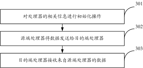
[0038] Based on the above structure, such as image 3 As shown, the data transmission method includes the following steps:

[0039] Step 301 , perform an initialization operation on related information of processors (source-end processor and destination-end processor). like Figure...

Embodiment 2

[0067] Based on the same inventive concept as the above method, an embodiment of the present invention also provides a data transmission device, which includes:

[0068] The IP protocol stack is used to perform fragmentation processing on the data packet to be sent when determining to fragment the data packet to be sent according to the size information of the data packet to be sent; and call the Rapid IO driver to send the processed fragment slice data;

[0069]Rapid IO driver, used to send processed fragmented data.

[0070] In the embodiment of the present invention, the device also includes:

[0071] The upper layer protocol software is used to send the information of the data packet to be sent to the IP protocol stack; wherein, the information of the data packet to be sent includes: the size information of the data packet to be sent and the destination IP address information.

[0072] In the embodiment of the present invention, the IP protocol stack is specifically used...

Embodiment 3

[0085] Based on the same inventive concept as the above method, an embodiment of the present invention also provides a data transmission device, which includes:

[0086] The IP protocol stack is used to classify the fragmented data according to the source IP address carried in the fragmented data after receiving the fragmented data from the incoming mailbox controller, and each IP address corresponds to a classification; and All fragmented data of this classification are taken as a complete data packet, and the data packet is stored in the receiving buffer provided by the upper layer protocol software.

[0087] In the embodiment of the present invention, the device also includes:

[0088] The call-in mailbox controller is used to call the receiving buffer information provided by the IP protocol stack to store the received fragmented data in the receiving buffer of the IP protocol stack after receiving the fragmented data.

[0089] In the embodiment of the present invention, t...


PUM


Abstract

The invention discloses a data transmission method and data transmission equipment. The method comprises that: when a data packet to be transmitted is determined to be fragmented according to the dimension information of the data packet to be transmitted, an internet protocol (IP) protocol stack fragments the data packet to be transmitted; and the IP protocol stack calls a rapid input / output (RapidIO) driver to transmit the processed fragmented data. In the method, by fragmenting the data packet to be transmitted through the IP protocol stack and transmitting the processed fragmented data through the RapidIO driver, the transmission rate can be improved; the RapidIO message transmission process is responsive transmission and belongs to reliable transmission; and if link congestion occurs, the data can finally reach an opposite terminal.

Description

technical field [0001] The present invention relates to the field of communication technology, in particular to a data transmission method and equipment. Background technique [0002] The IP (Internet Protocol, Internet Protocol) datagram fragmentation principle in the Ethernet network is specifically: in the IP protocol, due to the limitation of the maximum amount of data that can be carried by the link layer (called the maximum transmission unit MTU), When the size of the sent data payload exceeds the size of the MTU, the data cannot be delivered to the output link as a whole, so the data can be "fragmented" into two or more smaller datagrams, and then sent to the output link These smaller datagrams, called "slices", are sent on the computer. Among them, the slice needs to be reassembled before reaching the transport layer of the destination through the link layer, so that the receiver is located in the TCP (Transmission Control Protocol, Transmission Control Protocol) an...

Claims


Application Information

Patent Timeline
Patent Type & Authority Applications(China)
IPC IPC(8): H04L12/56H04L29/06H04L1/00
Inventor 王林李坤马明礼
Owner DATANG MOBILE COMM EQUIP CO LTD
Learn More