Video coding method and device and electronic equipment

A technology of video coding and prediction method, applied in the video field, can solve problems such as low accuracy and efficiency of bit rate control, time-consuming, deviation, etc., and achieve the effect of improving efficiency and accuracy and reducing coding complexity

Active Publication Date: 2011-04-27
HUAWEI TECH CO LTD +1
View PDF0 Cites 21 Cited by
  • Summary
  • Abstract
  • Description
  • Claims
  • Application Information

AI Technical Summary

Problems solved by technology

[0006] When using a fixed QP encoder to encode, continuous iterations are required to obtain QP. The encoding complexity is too high and the time is too long. Moreover, the final code rate obtained still has a large deviation from the target code rate, and the code rate control is accurate. Low degree and efficiency, high coding complexity

Method used


Image

  • Video coding method and device and electronic equipment
  • Video coding method and device and electronic equipment
  • Video coding method and device and electronic equipment

Examples


Embodiment 1

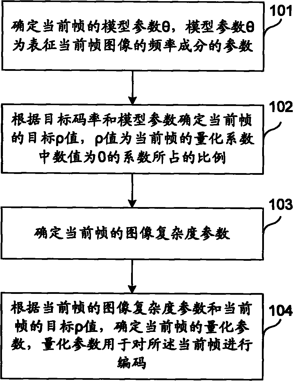
[0049] Based on the ρ-Qstep model established above, the video coding method provided by the embodiment of the present invention is as follows figure 2 shown, as figure 2 Shown is a flow chart of Embodiment 1 of the video encoding method of the present invention, including:

[0050] Step 101. Determine the model parameter θ of the current frame, where the model parameter θ is a parameter representing the frequency component of the current frame image.

[0051] Step 102: Determine the target ρ value of the current frame according to the target code rate and model parameters, and the ρ value is the proportion of the coefficients whose value is 0 in the quantization coefficients of the current frame.

[0052] Step 103. Determine the image complexity parameter of the current frame.

[0053] Step 104: Determine the quantization parameter of the current frame according to the image complexity parameter of the current frame and the target p value of the current frame, and the qua...

Embodiment 2

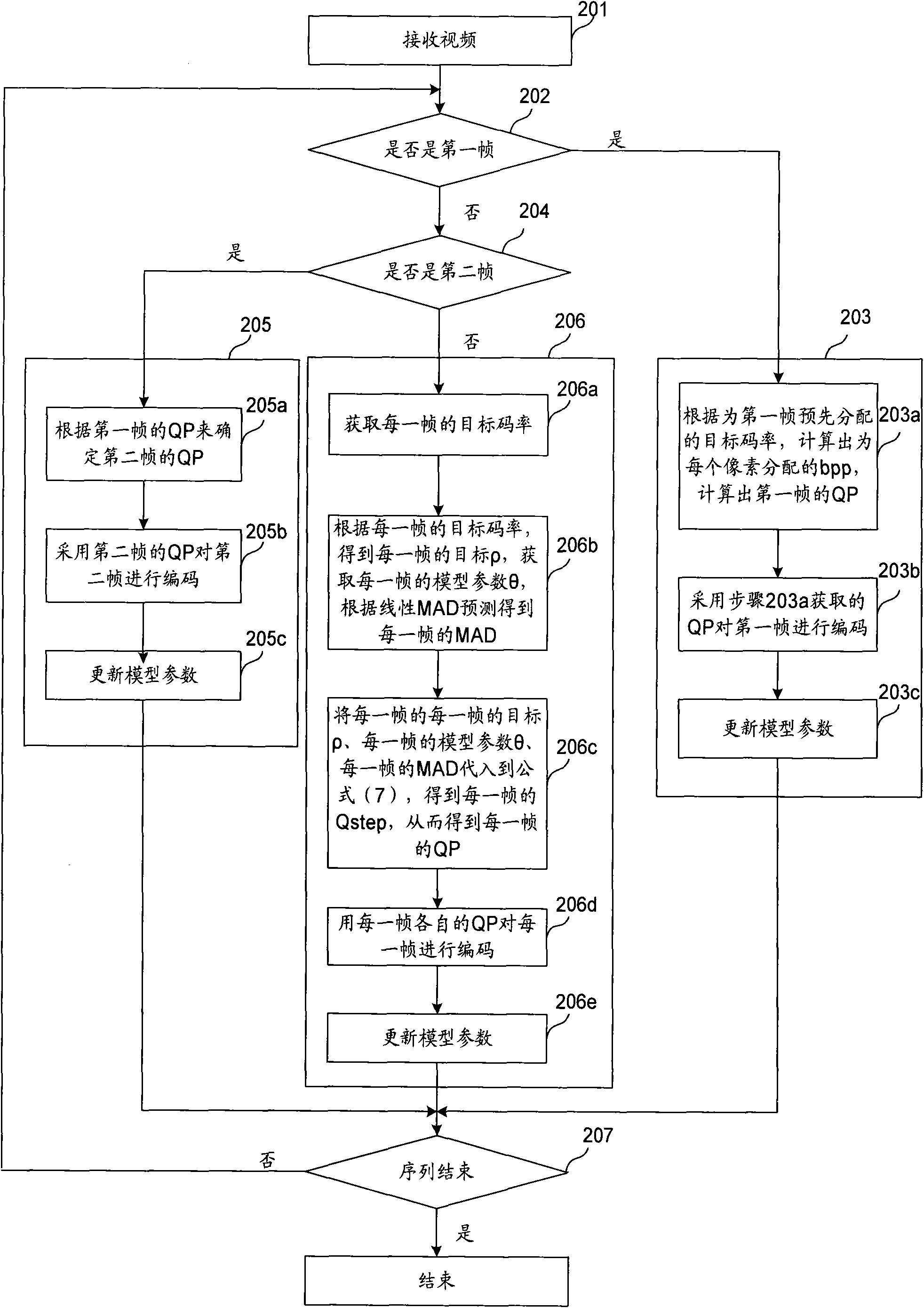
[0079] Such as image 3 Shown is the flow chart of Embodiment 2 of the video encoding method of the present invention, including:

[0080] Step 201, receiving video.

[0081] Step 202, judging whether the current frame is the first frame. If the current frame is the first frame, perform step 203; if the current frame is not the first frame, perform step 204.

[0082] Step 203 , perform code rate control on the first frame, and then execute step 207 .

[0083] Step 204, judge whether the current frame is the second frame, if the current frame is the second frame, execute step 205; if the current frame is not the second frame, execute step 206.

[0084] Step 205 , perform code rate control on the second frame, and then execute step 207 .

[0085] Step 206 , perform code rate control on other frames after the second frame, and then execute step 207 .

[0086] Step 207. Determine whether the video sequence is over, and if so, terminate the rate control; if the video sequence ...


PUM


Abstract

The embodiment of the invention discloses a video coding method, a video coding device and electronic equipment. The method comprises the following steps of: determining the model parameter theta of the current frame, wherein the model parameter theta represents the frequency component of the current frame image; determining the target rho value of the current frame according to a target code rate and the model parameter, wherein the rho value is the ratio of a coefficient of which the numerical value is 0 in the quantization parameter of the current frame; determining the image complexity parameter of the current frame; and determining the quantization parameter of the current frame according to the image complexity parameter of the current frame and the target rho value of the current frame, wherein the quantization parameter is used for coding the current frame. The method, the device and the electronic equipment of the embodiment of the invention can improve the efficiency and accuracy for code rate control and lower coding complexity.

Description

technical field [0001] The present invention relates to the field of video technology, in particular to a video encoding method, device and electronic equipment. Background technique [0002] When encoding a video sequence, the number of bits of the code stream generated per unit time is different. Therefore, on the communication channel, no matter whether the transmission rate is constant or variable, a buffer must be placed between the encoder and the channel. The larger the capacity of the buffer, the greater the ability to withstand changes in the code stream, but the greater the delay caused by buffering, that is, the capacity of the buffer is inversely proportional to the delay. At the same time, a code rate control system is needed to perform necessary control. The code rate control system can obtain the target bit rate for encoding according to the transmission channel and the fullness of the buffer zone, and then adjust the encoder based on the target code rate. Th...

Claims


Application Information

Patent Timeline
Patent Type & Authority Applications(China)
IPC IPC(8): H04N7/26H04N7/50H04N19/124H04N19/14
Inventor 刘猛郭宜李厚强杨名远胡昌启
Owner HUAWEI TECH CO LTD
Why Eureka
Try Eureka