Backlight module

A technology of backlight module and light source component, which is applied in the direction of optics, light guide, light source, etc., and can solve the problem of easy viewing of positioning pins, etc.

Inactive Publication Date: 2011-05-04
AU OPTRONICS CORP
View PDF0 Cites 15 Cited by
  • Summary
  • Abstract
  • Description
  • Claims
  • Application Information

AI Technical Summary

Problems solved by technology

[0005] However, since the current liquid crystal display frame gradually tends to adopt a narrow bezel design, it is easy for the user to see the positioning pin 34 when the viewing angle is large.

Method used


Image

  • Backlight module
  • Backlight module
  • Backlight module

Examples


Embodiment Construction

[0034] In order to further explain the technical means and effects of the present invention to achieve the intended purpose of the invention, the specific implementation, structure, characteristics and effects of the backlight module proposed according to the present invention will be described below in conjunction with the accompanying drawings and preferred embodiments. Details are as follows.

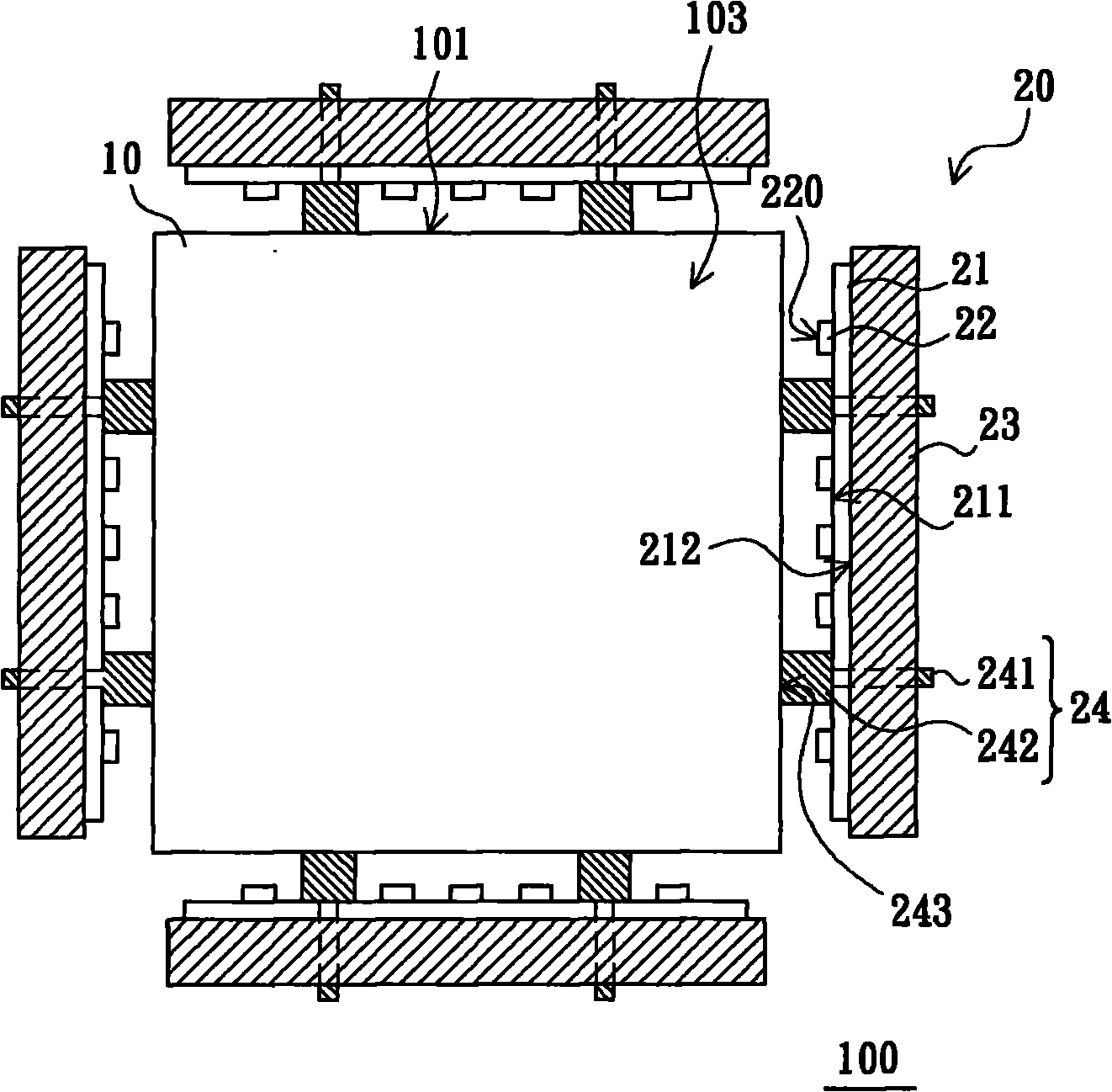
[0035] refer to figure 2 , which is a schematic top view of the backlight module provided by the first embodiment of the present invention. The backlight module 100 includes a light guide plate 10 and a plurality of light source assemblies 20. figure 2 In the figure, four light source assemblies 20 are taken as an example. The light guide plate 10 has a plurality of side surfaces 101 and a light-emitting top surface 103, and figure 2 In the figure, the four sides 101 are taken as an example. The light source assemblies 20 are respectively disposed beside the side surfaces 101 ...


PUM


Abstract

The invention provides a backlight module which comprises a light guide plate and at least one light source assembly arranged on one side of the light guide plate wherein the light source assembly comprises a substrate, a plurality of luminous elements, a heat radiation apparatus and at least one fixed part. The luminous elements are arranged on the bearing surface of the substrate along a predetermined direction; the heat radiation apparatus is connected with the substrate back side which is opposite to the bearing surface; the substrate is fixed on the heat radiation apparatus by the fixed part. Each fixed part possesses a head abutting against the substrate bearing surface wherein the head possesses a top face far from the bearing surface; the distance between the top face and the bearing surface is greater than that between the bearing surface and the light-emitting surface of each luminous element; the top face of the head is abutting against the side of the light guide plate. The backlight module does not need a positioning pin to fix a light guide plate thereby simplifying the flow of manufacturing and assembling and reducing production cost.

Description

technical field [0001] The invention relates to a backlight module, in particular to a side-light incident type backlight module. Background technique [0002] Liquid crystal display is already quite mature display technology at present. Since the liquid crystal display panel itself does not have luminous properties, a special backlight module is required to provide a uniform backlight for the liquid crystal display panel for display. Light emitting diodes (Light emitting diodes, LEDs) have gradually been widely used in backlight modules due to their excellent luminous performance and long lifespan. [0003] refer to figure 1 , which is a schematic top view of a side-illuminated backlight module using LEDs in the prior art. The backlight module 300 includes a light guide plate 30 and four light source modules 32 respectively disposed on four sides 301 of the light guide plate 30 . Each light source module 32 includes a substrate 321 , a plurality of LEDs 322 and a heat s...

Claims


Application Information

Patent Timeline
Patent Type & Authority Applications(China)
IPC IPC(8): F21S8/00F21V8/00F21V19/00F21V17/10F21V29/00G02F1/13357F21Y101/02F21V29/508F21V29/71
Inventor 林文新黄国正林苏逸柯雅华
Owner AU OPTRONICS CORP
Why Eureka
Try Eureka