Collecting pipe and processing method thereof

A processing method and header technology, applied in the field of fluid diversion devices in air-conditioning and refrigeration systems, can solve problems such as reduced product quality, uneven diversion, and reduced heat exchange capacity, so as to reduce the probability of failure and overcome the problem of branch nozzles Blocking and improving the energy efficiency of the whole machine

Inactive Publication Date: 2011-05-04
TCL AIR CONDITIONER ZHONGSHAN CO LTD
View PDF9 Cites 18 Cited by
  • Summary
  • Abstract
  • Description
  • Claims
  • Application Information

AI Technical Summary

Problems solved by technology

At present, the current collecting pipe of this structure has the following defects: because the matching gap between the branch pipe hole of the collecting pipe and the outer diameter of the branch pipe is very small, when using the brazing process commonly used on refrigeration appliances to weld the branch pipe, it is necessary to melt the metal electrode into a liquid The gap between the branch pipe hole and the branch pipe is full
Even when the branch pipe is a capillary tube, it is easy to cause the entire branch pipe orifice to be completely blocked
Once the branch pipe opening of the collecting pipe is blocked, the branch refrigeration pipes of the condenser or evaporator will have uneven distribution, and the heat exchange capacity will be reduced, which will seriously affect the refrigeration efficiency and even cause the failure of the refrigeration system
On the other hand, the current header blank tube is difficult to locate accurately when the branch pipe is welded, and it is prone to left and right deflection, which reduces the product quality and prevents the welded header from being effectively assembled on each branch refrigeration pipeline.

Method used


Image

  • Collecting pipe and processing method thereof
  • Collecting pipe and processing method thereof
  • Collecting pipe and processing method thereof

Examples


Embodiment Construction

[0028] The present invention will be further described below in conjunction with the accompanying drawings and specific embodiments.

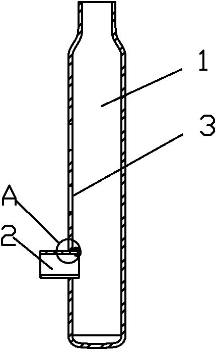
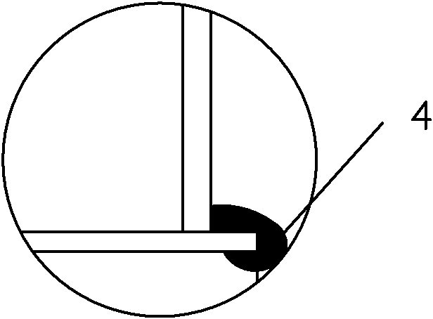
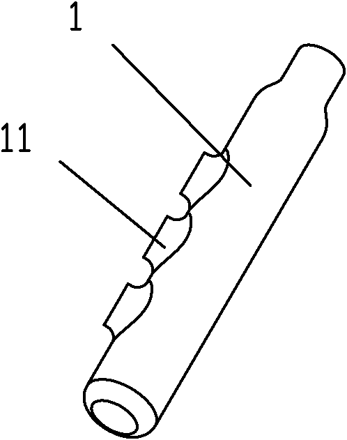
[0029] Collector of the present invention is welded by main pipe 1 and branch pipe 2, and the structure of main pipe is as image 3 As shown, three branch pipe holes 3 are provided on the main pipe, and outward branch pipe hole flanges 11 are provided on the branch pipe holes 3 . See Figure 4 , Figure 5 The branch pipe 2 is inserted into the main pipe from the branch pipe hole 3 of the main pipe 1. The outer diameter of the branch pipe matches the inner diameter of the branch pipe hole. , The solder pile 4 is stacked between the branch pipe and the flange of the branch pipe hole. There was no phenomenon of solder piles clogging the orifice.

[0030] The collecting pipe of the present invention is made by two processes of punching and edge drawing. A plurality of openings are punched on the blank tube wall of the collecting tube. The num...


PUM


Abstract

The invention discloses a collecting pipe which comprises a main pipe with a branch pipe hole, and a branch pipe and, wherein the branch pipe is welded on the branch pipe hole of the main pipe, and the branch pipe hole has an outward branch pipe hole flanging. The invention also discloses a processing method of the collecting pipe, which comprises the following steps that: a pipe blank is manufactured into the main pipe with the branch pipe hole flanging through punching and edge rolling processes, and then the branch pipe is welded on the main pipe. The collecting pipe overcomes the defect that the opening of the branch pipe is blocked due to capillarity during welding, makes a refrigeration system uniformly and stably distribute liquid, reduces the occurrence probability of refrigeration system faults, and can effectively improve the heat exchange capacity of a heat exchanger so as to increase the overall efficacy.

Description

technical field [0001] The invention relates to the technical field of fluid distribution devices for air-conditioning and refrigeration systems, and more specifically, to a header and a processing method thereof. Background technique [0002] The header is often used in refrigeration systems with multiple refrigerant separation branches, and is the node where multiple refrigerants converge in parallel. According to the phase state of the internal fluid, it can also be divided into a liquid collector and a gas collector. At the inlet and outlet ends of the evaporator of the air conditioning system, header pipes are commonly used to realize the diversion and convergence of refrigerant. The air pipe is then sucked into the compressor of the air conditioner through the main circuit of the refrigeration system. On the condenser or capillary tube of a large cooling capacity air conditioning system, the liquid collecting pipe is also commonly used to realize the diversion and co...

Claims


Application Information

Patent Timeline
Patent Type & Authority Applications(China)
IPC IPC(8): F28F9/02F25B39/00B23P15/00
Inventor 鲁益军
Owner TCL AIR CONDITIONER ZHONGSHAN CO LTD
Why Eureka
Try Eureka