

Motor commutator detection device
A technology of a motor commutator and a detection device, which is applied to measurement devices, electrical devices, motor generator testing, etc., can solve the problem of expensive, easy-to-burn data acquisition systems, and motor commutator radial runout detection errors and other problems, to achieve the effect of simple operation, accurate and reliable data, and user-friendly interface
- Summary
- Abstract
- Description
- Claims
- Application Information
AI Technical Summary
Problems solved by technology
Method used
Image

Examples
Embodiment 1
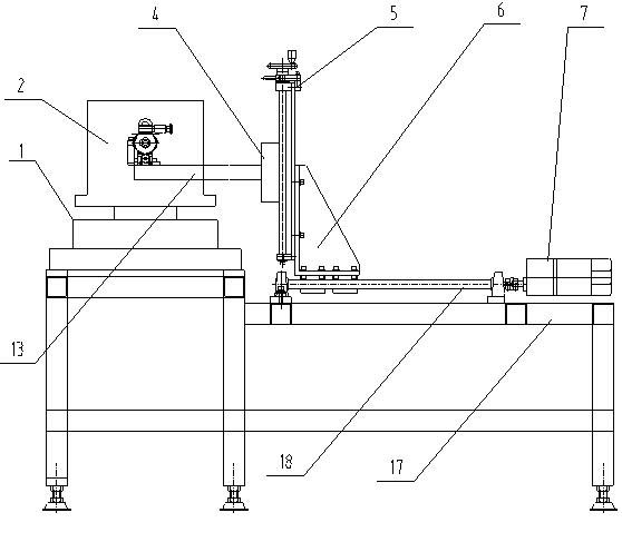
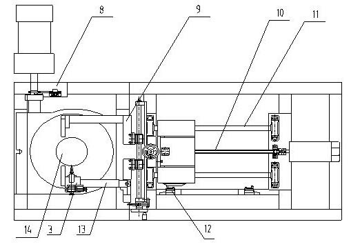
[0027] Embodiment one: see figure 1 and figure 2 , a deceleration motor is installed next to the rotary table 1, and the deceleration motor is connected to the photoelectric encoder 8 through a belt to read the rotation angle value. A linear moving device is installed on the base, and the linear moving device mainly includes a support plate 6, a gear motor 7, a screw rod 10, a guide rod 11, and a limit switch 12, which can drive the linear movement of the entire measuring device and facilitate the commutation of the motor. Clamping and unloading; the linear moving device is connected with the up and down moving mechanism 5 through the support plate 6, and the up and down moving mechanism 5 can realize up and down translation by shaking the hand wheel; the up and down moving mechanism 5 is connected with the lateral moving mechanism 4 through a slide plate, and the lateral moving mechanism 4 A forearm 13 is provided, and the double-ended electrode assembly 3 is housed on the ...
Embodiment 2
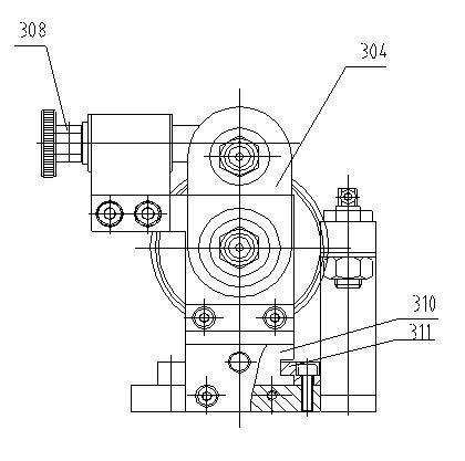
[0028] Embodiment 2: This embodiment is basically the same as Embodiment 1, and the special features are as follows: the double-headed electrode part 3, see image 3 and Figure 4 , 301 is the electrode head, 302 is the connecting nut, 303 is the electrode rod, 304 is the swing arm, 305 is the worm, 306 is the turbine, 307 is the screw, 308 is the hand wheel, 309 is the bracket, 310 is the sliding seat, 311 is Slide rail, 312 is handle. The double-headed electrode part is fixed on the forearm 13. After the forearm 13 is close to the motor commutator 2, the slider can be moved on the slide rail by rotating the nut on the slider, so that the electrode head 301 contacts the metal of the motor commutator. piece. One electrode head is connected to the swing arm 304, and the swing arm 304 is connected to the turbine 306 by screws. When the handwheel 308 is rotated, the turbine 306 can be driven, and then the swing arm 304 can rotate around the axis of the other electrode head, the...
PUM
 Abstract
Description
Claims
Application Information