Testing system and testing method of driver module of automobile electronic calibration software

A technology for driving modules and automotive electronics, applied in the field of automotive electronics calibration software driving module testing systems, can solve problems such as increasing system chain effects, wasting time and energy, lengthening system development cycles, and achieving the effect of improving safety and reliability.

Inactive Publication Date: 2011-05-04
重庆恩菲斯软件有限公司
View PDF4 Cites 5 Cited by
  • Summary
  • Abstract
  • Description
  • Claims
  • Application Information

AI Technical Summary

Problems solved by technology

And the basic functions and communication network services must be developed and tested before the development and testing of the calibration and diagnostic service modules can be carried out, which greatly reduces the system development efficiency and lengthens the system development cycle
At the same time, the independence of each module in the system cannot be guaranteed, which increases the chain effect of the system caused by the interdependence of each module
Such development often fails to complete the complete testing and verification of each component of the system, and is not conducive to product performance improvement and quality assurance
The development of the latter step of the module may lead to the rework of the previously developed components, and it is more likely to lead to the redevelopment of the previous steps of the module, resulting in a lot of waste of time and energy
Therefore, such development will cause a lot of waste of resources and time, which is not conducive to improving the efficiency of system development, and is not conducive to reducing development time and saving costs.

Method used


Image

  • Testing system and testing method of driver module of automobile electronic calibration software
  • Testing system and testing method of driver module of automobile electronic calibration software
  • Testing system and testing method of driver module of automobile electronic calibration software

Examples


Embodiment Construction

[0050] The technical solutions of the present invention will be further described in more detail in conjunction with the accompanying drawings and specific embodiments.

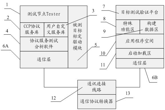
[0051] see figure 1 , an automotive electronic calibration software-driven module test system, consisting of test node Tester1, CCP protocol service library 2, user-defined service library 3, protocol service test analysis software 4, communication layers 6A, 6B, communication connection line 12, target test Verification platform 7 constitutes; Wherein

[0052] The test node Tester1 is used to run the protocol service test analysis software 4, execute the relevant commands and operations of the protocol service test analysis software 4, complete the function of the test host, realize the receiving and sending of test data and commands, provide test status display, and test The data and related analysis results are displayed; the program running on the test node Tester1 includes: CCP protocol service library ...


PUM


Abstract

The invention discloses a testing system of a driver module of automobile electronic calibration software. The testing system is characterized by comprising a test node Tester, protocol service test analysis unit, a CAN calibration protocol (CCP) protocol service library, a communication link line, a target test verification platform and a communication layer, wherein the test node Tester is used for operating the protocol service test analysis software, executing related commands and operations of the protocol service test analysis unit relative order and operation, finishing functions of a test host, realizing receiving and sending of test data and commands, providing test status display, and displaying the test data and related analysis results; the CCP protocol service library is developed on the basis of a CCP protocol and is used for providing standard CCP calibration service requests and related response services, and is invoked by the protocol service test analysis unit; and the protocol service test analysis unit invokes the CCP protocol service library to finish related service requests and responses specified in the CCP protocol service library, and provide analysis processing results.

Description

technical field [0001] The invention relates to the field of automotive electronic ECU development, in particular to an automotive electronic calibration software drive module testing system and method in compliance with the CCP protocol specification. Background technique [0002] In today's automotive electronic ECU development, an ECU embedded software often includes: basic functions, communication and network service functions, system calibration, diagnosis, test function services, and program update functions. In the current ECU embedded software development process, the entire software function part is often developed, and then the overall test and verification work is carried out. The entire development process is developed and tested according to the customary order, and the development of the next step module must wait It can only be carried out after the function of a step is completed. And the development and testing of the calibration and diagnostic service modu...

Claims


Application Information

Patent Timeline
Patent Type & Authority Applications(China)
IPC IPC(8): G06F11/36
Inventor 雷辉殷庆傅雪骄罗文明蒋鑫
Owner 重庆恩菲斯软件有限公司
Why Eureka
Try Eureka