Permanent magnet rotary motor

A technology of rotating electrical machines and permanent magnets, applied to synchronous motors with stationary armatures and rotating magnets, magnetic circuit rotating parts, magnetic circuit shape/style/structure, etc. It can increase the reluctance torque, reduce the material cost, and improve the demagnetization resistance.

Active Publication Date: 2011-05-04
FUJI ELECTRIC CO LTD
View PDF10 Cites 24 Cited by
  • Summary
  • Abstract
  • Description
  • Claims
  • Application Information

AI Technical Summary

Problems solved by technology

[0007] However, in the conventional example described in the aforementioned Patent Document 1, since the permanent magnet is formed in a reverse concave shape in which both ends are thicker than the central portion in the magnetization direction, it is necessary to cut the central portion of the rectangular parallelepiped magnet in order to form the permanent magnet. Alternatively, a mold with a concave shape is prepared in advance, and the mold is ejected. In addition, there is a method of forming a permanent magnet by combining concave and rectangular magnets, but there is an increase in the number of parts and man-hours for inserting the magnets into the grooves formed on the rotor. Unresolved issues such as increase in operating time, increase in processing costs, etc.

Method used


Image

  • Permanent magnet rotary motor
  • Permanent magnet rotary motor
  • Permanent magnet rotary motor

Examples


Embodiment Construction

[0043] Hereinafter, embodiments of the present invention will be described based on the drawings.

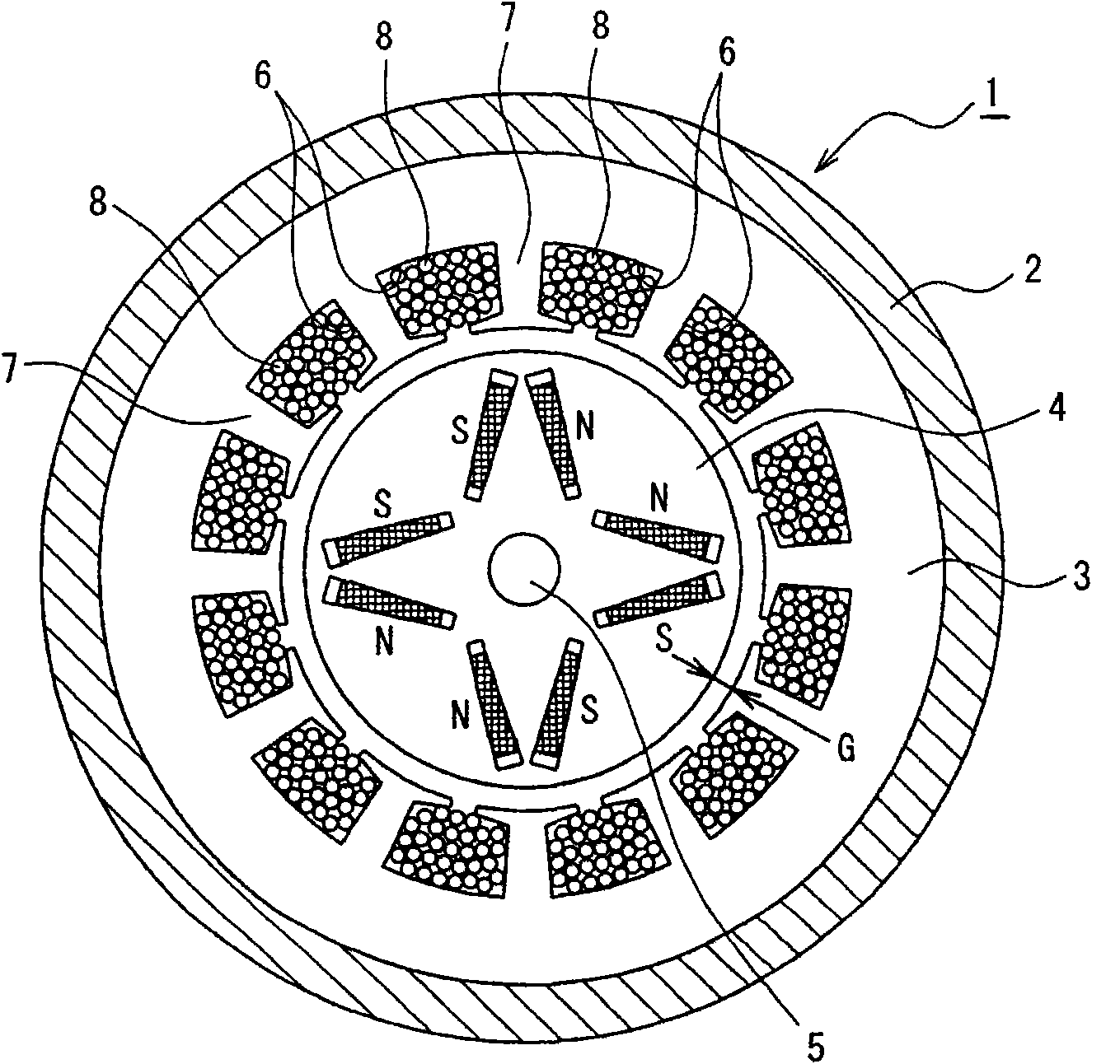
[0044] figure 1 It is a sectional view showing the first embodiment of the present invention. in the figure 1 Among them, the permanent magnet type rotating electrical machine 1 is constituted by an inner rotor type inner magnet type synchronous rotating electrical machine. This permanent magnet type rotating electrical machine 1 has a cylindrical frame 2 . On the inner peripheral side of the cylindrical frame 2, a cylindrical stator 3 is arranged, and on the inner peripheral side of the stator 3, a rotor 4 facing across a predetermined air gap G is arranged. The rotor 4 is supported by a rotating shaft 5 fitted in its center, and is rotatably arranged.

[0045] The stator 3 has, for example, 12 slots 6 and 12 teeth 7 formed at equal intervals in the circumferential direction on the inner peripheral surface side. An exciting coil 8 wound around each tooth 7 and fitted in th...


PUM


Abstract

The present invention provides a permanent magnet rotary motor which can ensure manufacturing facility of a permanent magnet, restrains manufacturing cost increase and improves demagnetization resistance. The permanent magnet rotary motor comprises the following components: a stator (3) which is coiled by energizing coils (8), and a rotor (4) which is separated from the stator (3) for a certain clearance and rotates relatively. The rotor (4) is provided with the following components: a plurality of grooves (13) which are formed in an axial direction in a rotor core (12); and permanent magnets (14) which are inserted into the groove (13) with a mode that the adjacent magnet poles (11a-11d) that are adjacent in a circumferential direction are different. The magnetic poles (11a-11d) respectively have a V-shaped structure which configures a pair of grooves (13) to expand to the stator (3). The permanent magnets (14) respectively represent a trapezium shape in which the width of at least the stator side in a magnetization direction to the stator (3) is enlarged.

Description

technical field [0001] The present invention relates to a permanent magnet (permanent magnet, permanent magnet) type rotating electrical machine including a stator and a rotor that rotates with a predetermined gap with respect to the stator and has a permanent magnet. Background technique [0002] An example of a conventional permanent magnet type rotating electrical machine includes a built-in magnet type rotating electrical machine. [0003] This built-in magnet type rotating electrical machine includes permanent magnets inside the rotor. This rotating electric machine utilizes the magnetic moment (torque) generated according to the magnetic flux generated by the permanent magnet and the interlinkage flux (interlinkage flux) of the field coil provided in the stator, and utilizes the magnetic resistance of the rotor core. Reluctance. The built-in magnet type rotating electrical machine is widely used as a small, high-power, high-efficiency rotating electrical machine. ...

Claims


Application Information

Patent Timeline
Patent Type & Authority Applications(China)
IPC IPC(8): H02K21/14H02K1/27
Inventor 岛田大志
Owner FUJI ELECTRIC CO LTD
Why Eureka
Try Eureka