Method for detecting position of rotor of permanent magnet motor

A technology of rotor position detection and permanent magnet motor, which is used in the control of generators, electronic commutators, motor generators, etc. Robust, accurate and stable rotor position

Active Publication Date: 2011-05-04
东元总合科技(杭州)有限公司
View PDF3 Cites 11 Cited by
  • Summary
  • Abstract
  • Description
  • Claims
  • Application Information

AI Technical Summary

Problems solved by technology

[0006] 3. Kalman filter method, the algorithm is complex and the parameters are difficult to adjust;
[0007] 4. Neural network method; the estimation method is relatively complicated, which makes the adjustment of the structure and the design of the parameters more difficult
[0008] In short, the above methods either rely heavily on the motor parameters, and once the motor parameters change greatly (such as air-conditioning compressors, etc.), it will cause a large error in the estimation of the rotor position; or the algorithm is complicated, and the parameter adjustment is complicated and difficult. Very susceptible to external conditions, poor adaptability

Method used

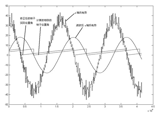
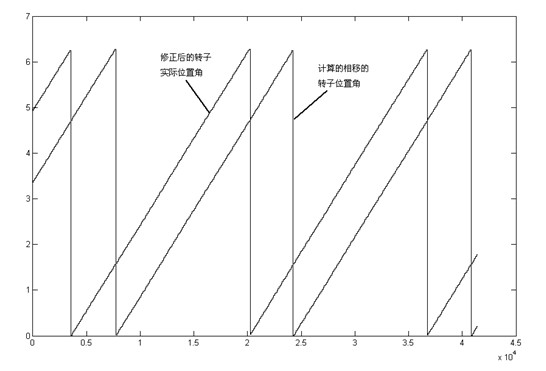
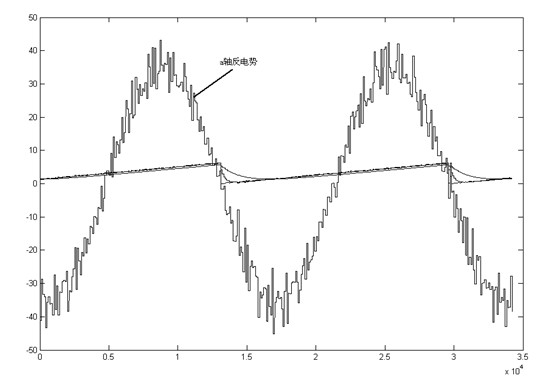

Image

  • Method for detecting position of rotor of permanent magnet motor
  • Method for detecting position of rotor of permanent magnet motor
  • Method for detecting position of rotor of permanent magnet motor

Examples


Embodiment Construction

[0029] In order to make the technical means, creative features, goals and effects achieved by the present invention easy to understand, the present invention will be further described below in conjunction with specific illustrations.

[0030] The gist of the present invention is to solve the problem that sensorless control of permanent magnet motors is used in the prior art, and the rotor position detection method of permanent magnet motors is cumbersome and particularly sensitive to motor parameters (resistance R, inductance L), and provides a permanent magnet motor based on back EMF Magnetic motor rotor position detection method.

[0031] As mentioned in the background technology, there are many methods for detecting the rotor position of a permanent magnet motor, each of which has its own advantages and corresponding disadvantages. In addition to the methods mentioned in the background technology, the detection of the rotor position of a permanent magnet motor can also be pe...


PUM


Abstract

The invention provides a method for detecting the position of a rotor based on counter potentials of a permanent magnet motor, aiming at overcoming the defects that the traditional methods for detecting the position of the rotor are complex and depend on motor parameters. The method is characterized by after filtering alpha axis counter potential and beta axis counter potential in an alpha-beta coordinate system of the permanent magnet motor, calculating the position of the rotor after phase shifting, and obtaining the actual position of the rotor according to the influence of the predetermined filtering frequency and the predetermined number of filtering times on the phase of the rotor. The method has the following beneficial effects: various spurious signals in the counter potential calculation results can be effectively eliminated to remain the actual signals, thus the estimated position of the rotor is more accurate and stable; and the estimated position of the rotor dispenses with additional check or correction under the condition that the important motor parameters are obviously changed or the range of the motor parameters can be only roughly determined, thus greatly improving the robustness of an observer and being convenient for engineering application and implementation.

Description

technical field [0001] The invention relates to the technical field of motor control, in particular to a method for detecting the rotor position of a permanent magnet motor. Background technique [0002] The permanent magnet motor needs to detect the position of the rotor to realize the commutation of the winding during operation. This is the basis for controlling the permanent magnet motor. The accuracy of the rotor position detection of the permanent magnet motor directly affects the control effect of the permanent magnet motor. Due to the high failure rate of the rotor position sensor, which will reduce the reliability of the entire system, the detection of the permanent magnet motor rotor position has transitioned from sensor detection to sensorless estimation. [0003] In the prior art, in the control method of position sensorless permanent magnet motor, many methods have been proposed to estimate the position and speed of the motor rotor, for example: [0004] 1. ...

Claims


Application Information

Patent Timeline
Patent Type & Authority Applications(China)
IPC IPC(8): H02P21/00H02P6/16H02P6/182H02P21/18
Inventor 叶林华邹积浩
Owner 东元总合科技(杭州)有限公司
Why Eureka
Try Eureka