Method for solving problem of adjacent channel interference through multi-antenna co-location

A technology of adjacent channel interference and cooperative positioning, applied in the field of accurate identification of vehicle electronic tags, can solve problems such as adjacent channel interference and wrong transactions in the ETC system, and achieve the effect of eliminating adjacent channel interference

Active Publication Date: 2011-05-04
北京速通科技有限公司
View PDF3 Cites 33 Cited by
  • Summary
  • Abstract
  • Description
  • Claims
  • Application Information

AI Technical Summary

Problems solved by technology

[0003] For the current ETC toll collection system, the main problem is the interference of adjacent lanes of the ETC system: the signal emitted by the antenna of the roadside equipment on this lane radiates to the adjacent lane, or the antenna of the roadside equipment on this lane receives the electronic signals from the vehicle on the adjacent lane. The signal of the label, thus causing the phenomenon of wrong transaction
If the No. 2 antenna 203 of the electronic non-stop charging lane 2 trades with the vehicle 101, there will also be a wrong transaction phenomenon

Method used


Image

  • Method for solving problem of adjacent channel interference through multi-antenna co-location
  • Method for solving problem of adjacent channel interference through multi-antenna co-location
  • Method for solving problem of adjacent channel interference through multi-antenna co-location

Examples


Embodiment 1

[0036] The present invention is a multi-antenna cooperative positioning method to solve the problem of adjacent channel interference. The data of antenna, solve adjacent channel interference, it is characterized in that: the method comprises the following steps:

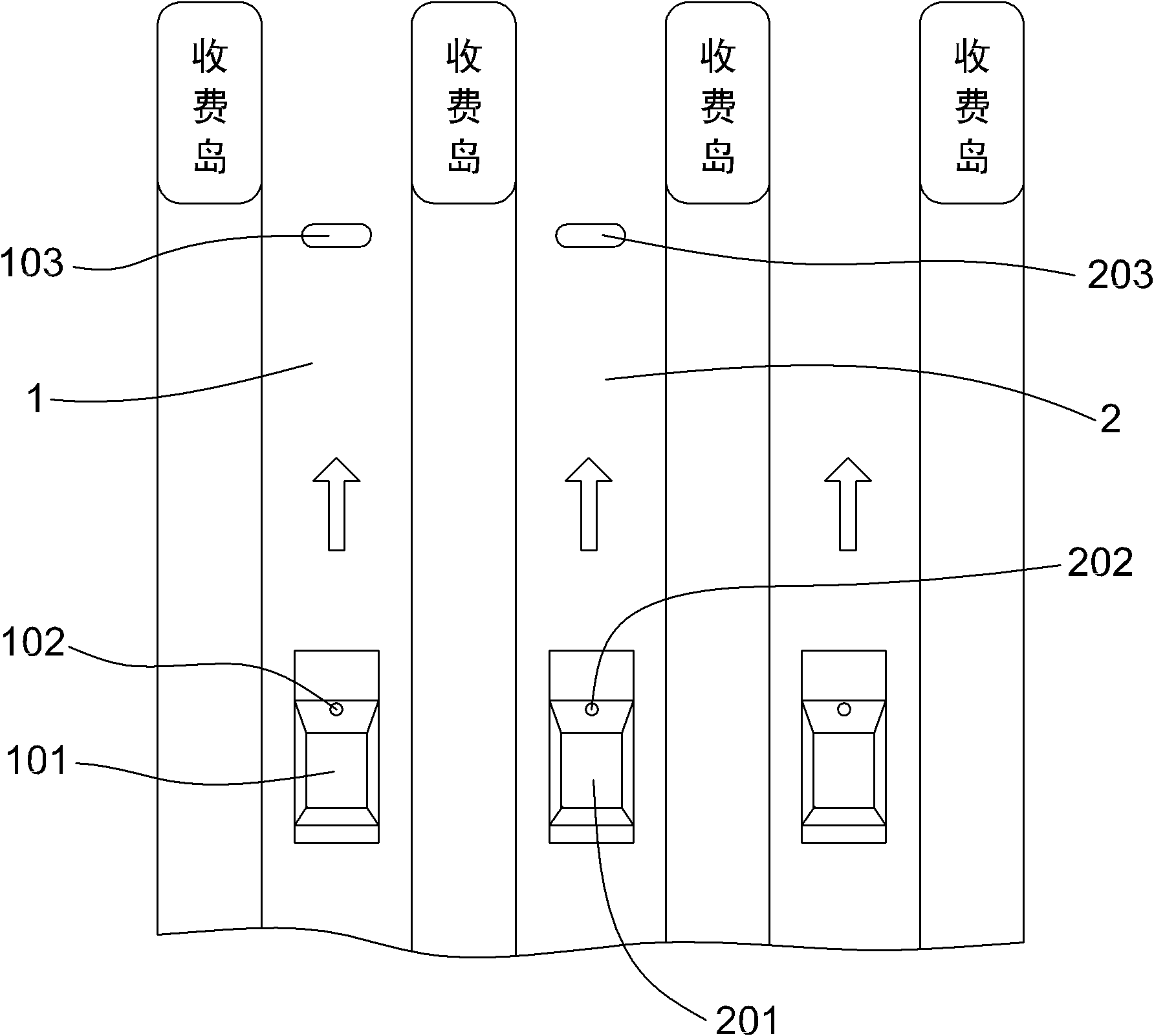
[0037] Step 1: Set a reference line inside the detection area of ​​the No. 1 antenna and the No. 2 antenna. The reference line is perpendicular to the driving direction. According to the span between the No. 1 antenna and the No. 2 antenna, divide the reference line by equal steps punctuation;

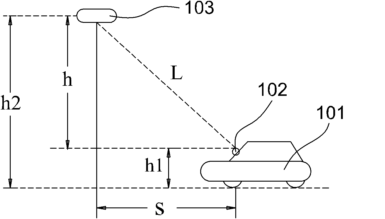
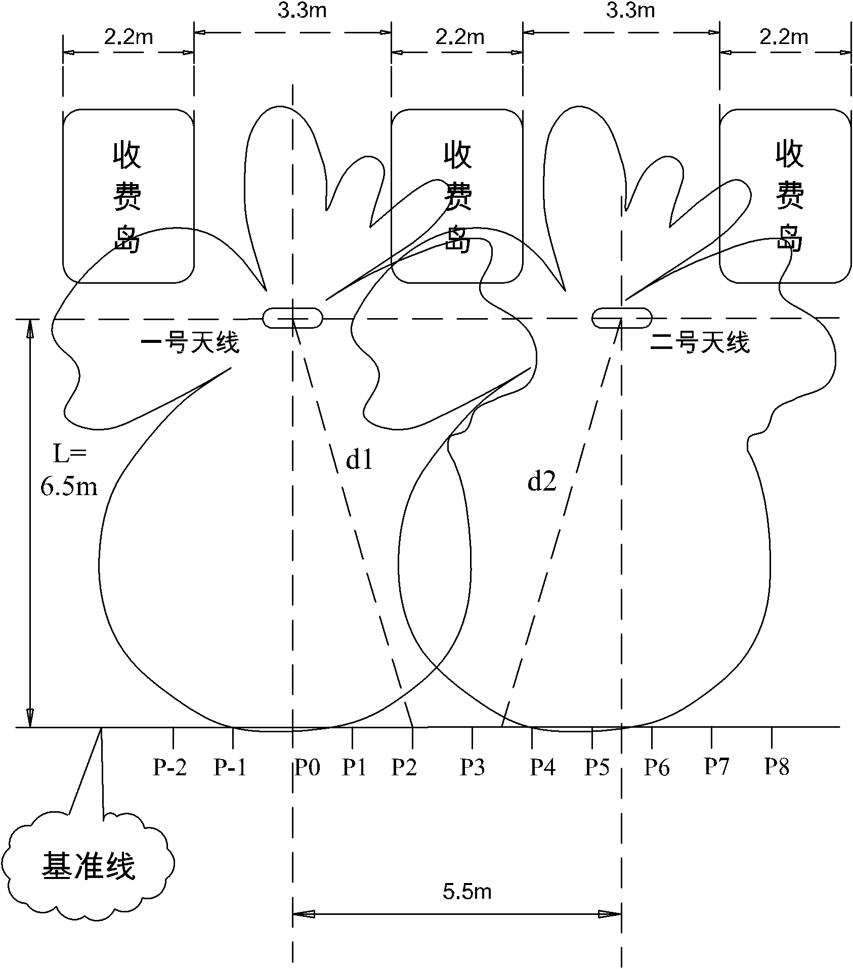
[0038] In this embodiment, the No. 1 antenna and the No. 2 antenna are respectively installed in the center of their respective lanes on the gantry frame, the installation height is 5.5 meters, and the installation angle is 45 degrees downward. The same graph, such as image 3 As shown, the horizontal direction of the maximum antenna radiation power is the center of the lane, and the vertical direction is the middle part of...

Embodiment 2

[0133] Embodiment 2, the present invention is a method for multi-antenna cooperative positioning to solve the problem of adjacent lane interference. The method is used for two or more electronic non-stop charging antenna systems arranged side by side. Antenna and No. 2 antenna data, solve adjacent channel interference, it is characterized in that: the method comprises the following steps:

[0134] Step 1: Set a reference line inside the detection area of ​​the No. 1 antenna and the No. 2 antenna. The reference line is perpendicular to the driving direction. According to the span between the No. 1 antenna and the No. 2 antenna, divide the reference line by equal steps punctuation;

[0135] In this embodiment, the No. 1 antenna and the No. 2 antenna are respectively installed in the center of the respective lanes on the gantry frame, the installation height is 5.5 meters, and the installation angle is 45 degrees downward. The horizontal direction of the maximum radiation power o...


PUM


Abstract

The invention discloses a method for solving a problem of adjacent channel interference through multi-antenna co-location, and the method is applied to parallelly-arranged ETC (electronic toll collection) antenna systems. The method comprises the following steps: 1, dividing scaling points; 2, calculating the distances between the scaling points and No.1 and No.2 antennas; 3, determining the basic link transmission losses of the No.1 antenna and the No.2 antenna relative to the scaling points; 4, theoretically calculating an uplink signal strength value of each scaling point received by a No.1 antenna receiver; 5, theoretically calculating an uplink signal strength value of each scaling point received by a No.2 antenna receiver; 6, adjusting the uplink signal strength value of each scaling point received by the No.1 antenna receiver through actual measurement so as to obtain a reference value; 7, adjusting the uplink signal strength value of each scaling point received by the No.2 antenna receiver so as to obtain a reference value; and 8, through carrying out matched fitting with the reference values, determining the position of a vehicle. By utilizing the method provided by the invention, the problem of adjacent channel interference can be solved, and the reliability of the ETC antenna system can be improved.

Description

technical field [0001] The invention relates to the electronic non-stop toll collection technology in the intelligent traffic system, in particular to a method for accurately identifying vehicle electronic tags in the electronic toll collection system. Background technique [0002] The Electronic Toll Collection (ETC) system is an electronic automatic toll collection system for highways, bridges and tunnels that is being developed and promoted internationally. Through the microwave dedicated short-range communication between the vehicle electronic tag installed on the vehicle windshield and the antenna on the road side of the ETC lane of the toll station, the computer networking technology is used to carry out settlement processing with the background toll center, so that the vehicle passes through the road and bridge toll station without needing to pay. The purpose of automatically paying road and bridge tolls for parking. [0003] For the current ETC toll collection syste...

Claims


Application Information

Patent Timeline
Patent Type & Authority Applications(China)
IPC IPC(8): H04B17/00H04B7/04G07B15/00
Inventor 张为民张北海薛金银李全发张明月高文宝张晶晶
Owner 北京速通科技有限公司
Why Eureka
Try Eureka