
Laser machining method, laser machining device and chip manufacturing method

A laser processing method and laser processing technology, which are applied to fine working devices, manufacturing tools, stone processing equipment, etc., can solve the problems of reduced wafer splitting, device layer damage, etc.

Inactive Publication Date: 2011-05-11
DISCO CORP
View PDF8 Cites 4 Cited by
  • Summary
  • Abstract
  • Description
  • Claims
  • Application Information

AI Technical Summary

Problems solved by technology

When there is an unprocessed area in which no processing groove is formed, not only the splittability of the wafer is reduced, but also the laser beam that is not absorbed by the sapphire substrate is irradiated to the device layer, causing damage to the device layer

Method used


Image

  • Laser machining method, laser machining device and chip manufacturing method
  • Laser machining method, laser machining device and chip manufacturing method
  • Laser machining method, laser machining device and chip manufacturing method

Examples


Embodiment Construction

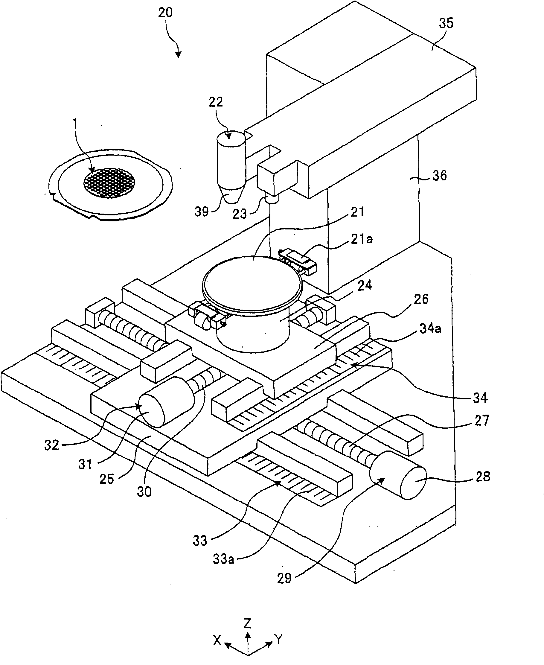
[0047] Hereinafter, a laser processing apparatus, a laser processing method, and a chip manufacturing method including the laser processing method, which are preferred embodiments for carrying out the present invention, will be described with reference to the drawings. This embodiment shows an example applied to the case where a laser beam is irradiated to a transparent substrate of a wafer on which a functional layer is formed on the surface of the transparent substrate and a plurality of lanes arranged in a grid pattern are used to perform ablation processing. Devices are formed in the plurality of divided regions.

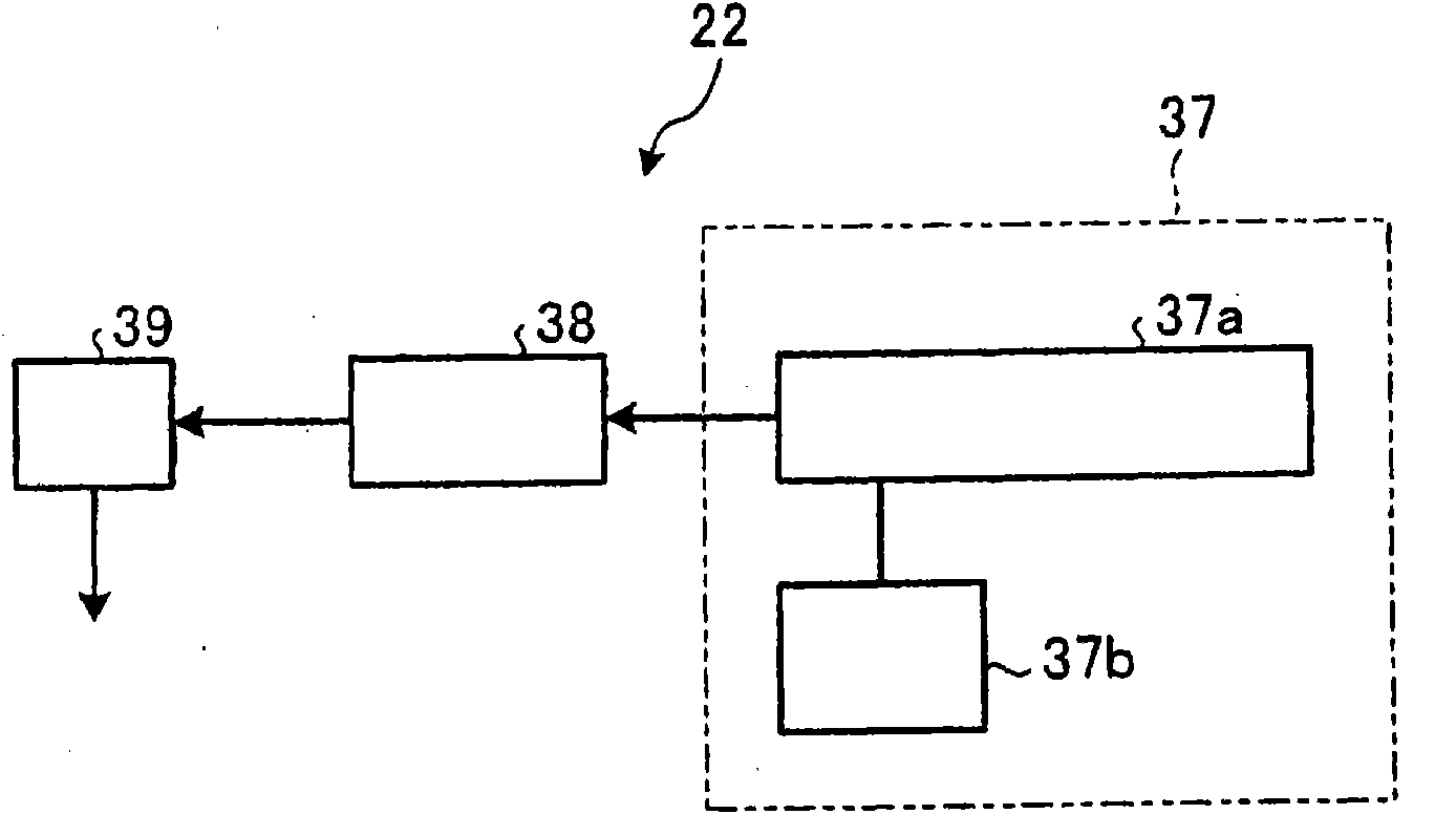
[0048] figure 1 It is an external perspective view showing the main part of the laser processing apparatus of this embodiment, figure 2 It is a schematic block diagram showing a configuration example of a processing unit. The laser processing device 20 of the present embodiment has: a holding unit 21 for holding a wafer 1; a processing unit 22 for performing...


PUM

PropertyMeasurementUnit
thicknessaaaaaaaaaa
wavelengthaaaaaaaaaa
thicknessaaaaaaaaaa

Abstract

The invention provides a laser machining method, a laser machining device and a chip manufacturing method. According to the invention, machining grooves for segmenting a transparent substrate, such as a sapphire substrate, can be reliably formed, and the fusion layer on the cut surface of a chip can be lowered, thereby minimizing the quality degradation. A spacing track (4) of a wafer (1) is alternately provided with machining regions (G) for forming machining grooves (210) and machining start regions (H) for forming shallow grooves (211) which are shallower than the machining grooves (210), so that an irradiation point (P) of a laser beam can scan along the spacing track (4), thereby continuously forming the machining grooves (210) and the shallow grooves (210).

Description

technical field [0001] The present invention relates to a laser processing method for ablation (ablation) processing by irradiating a laser beam on a transparent substrate of a wafer having a functional layer formed on the surface of the transparent substrate, a laser processing device and a chip manufacturing method. Devices are formed in a plurality of regions formed by a plurality of grid-like channels. Background technique [0002] In the manufacturing process of a semiconductor device, a plurality of regions are divided on the surface of a roughly disc-shaped semiconductor wafer by dividing lines called streets arranged in a grid, and among these divided regions Form IC, LSI and other circuits. Then, the semiconductor wafer is cut along the lanes, divided into regions where devices are formed, and individual semiconductor chips are manufactured. In addition, an optical device wafer in which light-emitting elements such as light-emitting diodes (LEDs) are stacked on th...

Claims


Application Information

Patent Timeline
Patent Type & Authority Applications(China)
IPC IPC(8): B23K26/00B28D5/04H01L21/00H01L33/00B23K26/364
Inventor 远藤智裕
Owner DISCO CORP
Learn More