Air-cooled dry-type slag discharging system

A dry slag removal and air-cooling technology, which is applied to lighting and heating equipment, can solve the problems of cost increase and achieve sufficient cooling effect

Active Publication Date: 2011-05-11
BEIJING GUODIAN FUTONG SCI & TECH DEV
View PDF5 Cites 11 Cited by
  • Summary
  • Abstract
  • Description
  • Claims
  • Application Information

AI Technical Summary

Problems solved by technology

[0005] The technical problem to be solved by the present invention is that the wet slag removal system in the prior art cannot be installed along the length direction to directly extend to the slag bin due to equipment obstruction, and if it is installed along the width direction, it needs to be arranged side by side Set up multiple steel belt slag conveyors, which will directly lead to a great increase in cost, and then provide an air-cooled dry slag discharge system suitable for the transformation of the above wet slag removal system

Method used


Image

  • Air-cooled dry-type slag discharging system
  • Air-cooled dry-type slag discharging system
  • Air-cooled dry-type slag discharging system

Examples


Embodiment Construction

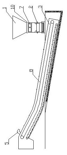
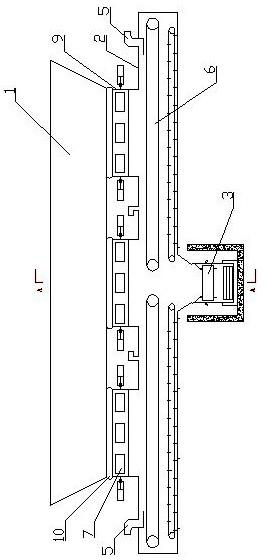
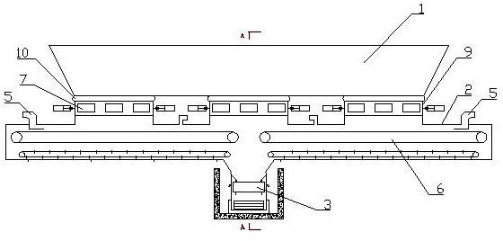
[0023] The air-cooled dry slag discharge system described in the present invention is as figure 1 , figure 2 As shown in the figure, it can be seen from the figure that the air-cooled dry slag discharge system includes a slag well 1, the upper end of which is connected to the slag discharge outlet of the boiler, and the longitudinal section of the slag well 1 is funnel-shaped. It also includes a steel belt slag conveyor sealing box 2, which is arranged along the length direction of the boiler slag discharge port in the steel belt slag conveyor sealing box 2, and the length of the steel belt slag conveyor sealing box 2 is the same as The length of the bottom of the slag well 1 is suitable. The bottom of the slag well 1 can be directly connected to the top of the sealed box 2 of the steel belt slag conveyor, or can be connected to the sealed box of the steel belt slag conveyor through one or more furnace bottom slagging devices 9 2 are connected at the top. The furnace botto...


PUM


Abstract

The invention provides an air-cooled dry-type slag discharging system modified by a hydraulic slag removing system, which comprises a slag well and a sealed tank body of a steel-belt slag conveyor, wherein the upper end of the slag well is connected with a boiler slag discharging hole; the longitudinal cross section of the slag well is funnel-shaped; the top end of the sealed tank body of the steel-belt slag conveyor is communicated with the bottom end of the slag well; one or more air inlets are also formed on the sealed tank body of the steel-belt slag conveyor; the sealed tank body of the steel-belt slag conveyor is arranged in the length direction of the boiler slag discharging hole; two conveyor belts (for oppositely conveying slag) of the steel-belt slag conveyor are arranged in the sealed tank body of the steel-belt slag conveyor; a space for allowing the slag to fall into is formed between the two conveyor belts of the steel-belt slag conveyor; and a secondary slag discharging device is also included, wherein the secondary slag discharging device is arranged in the width direction of the boiler slag discharging hole, and a secondary conveyor belt of the steel-belt slag conveyor is arranged in the secondary slag discharging device and arranged below the space. The air-cooled dry-type slag discharging system has the advantages of evenly and fully cooled high-temperature slag, lower requirement to the space, simple structure and reasonably utilized space, and achieves the purpose of modifying the slag removing system into the dry-type slag discharging system.

Description

technical field [0001] The invention relates to a high-temperature ash discharge and conveying system at the furnace bottom of a coal-fired boiler in a power station, in particular to an air-cooled dry slag discharge system. Background technique [0002] The dry slag discharge system in the prior art is mainly composed of an air-cooled dry steel belt slag conveyor, a centralized conveying system and a slag storage system. While the steel belt slag conveyor is conveying the hot slag discharged from the boiler, a certain amount of ambient air is sucked in by the negative pressure of the boiler. The temperature of the slag itself is lowered, the ash and slag is sent to the slag storage bin after cooling, and the ambient air that absorbs the heat of the ash and slag is returned to the furnace from the slag outlet of the boiler, thereby improving the thermal efficiency of the boiler. Compared with the traditional hydraulic slag removal system, the air-cooled dry slag removal sys...

Claims


Application Information

Patent Timeline
IPC IPC(8): F23J1/06
Inventor 朱夏宁张晶
Owner BEIJING GUODIAN FUTONG SCI & TECH DEV
Why Eureka
Try Eureka